Bidirectional earth leakage circuit breaker

A leakage protection and circuit breaker technology, applied in electromagnetic release switches, switches operated by ground fault current, etc., to achieve the effects of saving production investment, saving mold investment, and reliable and convenient wiring

Inactive Publication Date: 2011-02-16
戴英夫
View PDF3 Cites 2 Cited by
  • Summary
  • Abstract
  • Description
  • Claims
  • Application Information

AI Technical Summary

Problems solved by technology

[0003] In order to overcome the problem that the existing electronic leakage protection circuit breaker cannot have the lower end as the power input terminal and the upper end as the load output terminal, the present invention provides a bidirectional leakage protection circuit breaker

Method used


Image

  • Bidirectional earth leakage circuit breaker
  • Bidirectional earth leakage circuit breaker
  • Bidirectional earth leakage circuit breaker

Examples


Embodiment Construction

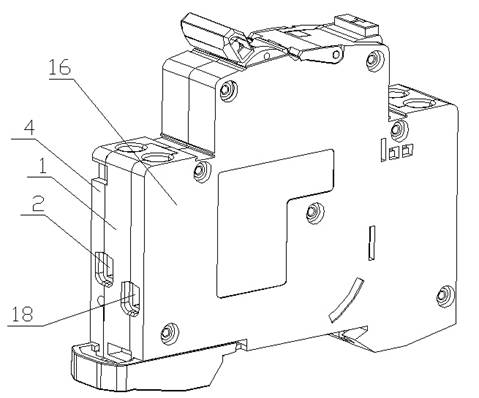
[0015] The external structure of the bidirectional leakage protection circuit breaker is as follows: figure 1 As shown, the base 4 and the cover 16 are divided into two spaces by a partition device 1. The lower part of the partition device 1 is the neutral line of the bidirectional leakage protection circuit breaker, and the upper part of the partition device 1 is the live wire of the bidirectional leakage protection circuit breaker. .

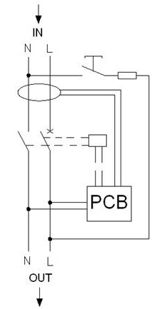
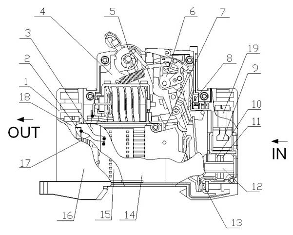
[0016] The upper end of the bidirectional leakage protection circuit breaker is the power inlet end, and the lower end is the load outlet end. The electrical schematic diagram is as follows figure 2 shown. The overall structure of the bidirectional leakage protection circuit breaker is as follows: image 3 and Figure 4 As shown, the right neutral terminal 19 and the right live terminal 9 are the incoming terminals of the bidirectional earth leakage protection circuit breaker, and the right neutral terminal 19 and the right live terminal 9...


PUM


Abstract

The invention discloses a bidirectional earth leakage circuit breaker. When a right zero line electrode terminal and a right live line electrode terminal of the breaker are input terminals of the bidirectional earth leakage circuit breaker, a circuit board zero-line power line on a circuit board is connected with a left zero line electrode terminal, and a circuit board live-line power line on the circuit board is connected with a left live line electrode terminal; and when the left zero line electrode terminal and the left live line electrode terminal are the input terminals of the bidirectional earth leakage circuit breaker, the circuit board zero-line power line on the circuit board is connected with the right zero line electrode terminal, and the circuit board live-line power line on the circuit board is connected with a live line electric conduction system. The bidirectional earth leakage circuit breaker in the invention not only can provide a line connection mode that the upper end of a traditional electronic earth leakage circuit breaker is a power line incoming terminal and the lower end of the same is a load line outgoing terminal, but also can be set into a line connection mode that the lower end of the traditional electronic earth leakage circuit breaker is the power line incoming terminal and the upper end is the load line outgoing terminal, therefore, the usage range and the application area of the earth leakage circuit breaker are enlarged, the line connection is reliable, convenient and rapid, the structure is simple, and large amount of production investment and mould investment is saved.

Description

technical field [0001] The invention relates to the field of circuit breakers, in particular to a leakage protection circuit breaker. Background technique [0002] At present, the structure of electronic leakage protection circuit breaker is composed of terminals, electromagnetic system, handle operating mechanism, static contact, moving contact, conductive system, magnetic ring, double gold system, circuit board, arc extinguishing cover, base, cover and partition Generally, the electronic leakage detection and sensing system of the leakage protection circuit breaker must be located at the load end of the leakage protection circuit breaker, so that the electronic leakage detection and sensing system will not fail when the line fails and the leakage protection circuit breaker is disconnected. will be burned. However, due to the limited internal space of the traditional electronic leakage protection circuit breaker, the placement position of the internal components of the lea...

Claims


Application Information

Patent Timeline
Patent Type & Authority Applications(China)
IPC IPC(8): H01H73/36H01H83/02
Inventor 戴英夫蒋俊勋
Owner 戴英夫
Why Eureka
Try Eureka