A deep tissue continuous suture tool used with microscope or endoscope

A deep tissue and endoscope technology, applied in the field of medical devices, can solve the problems of long training time, inaccurate operation, long operation time, etc., and achieve the effect of simple design and convenient use

Active Publication Date: 2019-02-12
NANFANG HOSPITAL OF SOUTHERN MEDICAL UNIV
View PDF6 Cites 0 Cited by
  • Summary
  • Abstract
  • Description
  • Claims
  • Application Information

AI Technical Summary

Problems solved by technology

In the traditional endoscopic channel for surgical operation, because the endoscopic channel is narrow and overall long, the design of the instruments passing through it is slender, and the tail end controlled during operation is far away from the working head end, resulting in inaccurate operation. The operation is slow and takes a long time
Secondly, in endoscopic endoscopic surgery, because the operating end of the instrument is located at the end of the endoscopic lens, the large double-ring structure and needle thread in the suturing operation, in the enlarged field of view, its small movement will cause the working end to be unclear.
This invention patent can neither break away from the stereotype of endoscopic surgery. The common problems of endoscopic surgery are inconvenient operation, longer operation time and longer training time, which are more prominent in this invention patent.

Method used


Image

  • A deep tissue continuous suture tool used with microscope or endoscope
  • A deep tissue continuous suture tool used with microscope or endoscope
  • A deep tissue continuous suture tool used with microscope or endoscope

Examples


Embodiment Construction

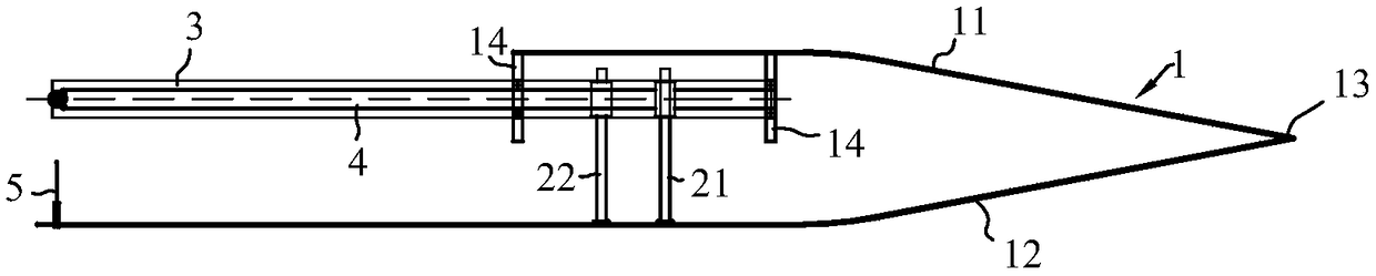
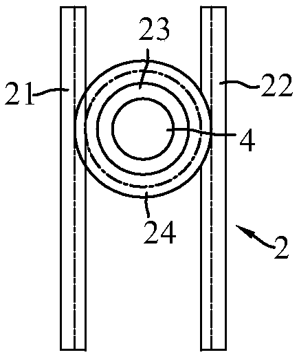
[0026] refer to Figure 1 to Figure 5 , which shows the specific structure of the preferred embodiment of the present invention. The structural characteristics of each element of the present invention will be described in detail below, and if there is a description of the direction (up, down, left, right, front and back), it is based on figure 1 The shown structure is a reference description, but the actual use direction of the present invention is not limited thereto.

[0027] The invention provides a deep tissue continuous suture tool used in conjunction with a microscope or an endoscope, see figure 1 , figure 2 , including tweezers 1 and a rotating shaft drive mechanism 2, tweezers 1 includes an upper tweezers body 11, a lower tweezers body 12 and a handle 13 fixedly connecting the upper tweezers body 11 and the lower tweezers body 12, and the tweezers 1 is preferably a gun-shaped tweezers. The gun-shaped tweezers 1 is used as the main part and the force application par...


PUM


Abstract

The invention discloses a deep tissue continuous suturing tool matching with a microscope or an endoscope in use, which is applied to the technical field of medical devices. The deep tissue continuous suturing tool comprises a pair of tweezers and a rotary shaft driving mechanism, wherein the tweezers comprise an upper tweezers body, a lower tweezers body and a handle fixedly connecting the upper tweezers body and the lower tweezers body, a shaft sleeve is arranged on the upper tweezers body, a rotating shuttle mechanism is arranged at a remote end of the shaft sleeve and comprises a rotating shuttle and a line shaft, a rotary shaft capable of driving the rotating shuttle to rotate is arranged in the shaft sleeve, a suturing needle correspondingly matching with the rotating shuttle mechanism is arranged at the remote end of the lower tweezers body, and a needle hole is formed in a tip of the suturing needle. The upper tweezers body and the lower tweezers body are pressed down and then are loosened, the rotary shaft driving mechanism can rotate a circle around the rotating shuttle, and meanwhile, the suturing needle and the rotating shuttle mechanism match to complete once suturing operation. The deep tissue continuous suturing tool imitates the design of the tweezers usually used in a surgery deep operation, so that the use is convenient, the space occupation rate is minimum, components are simple, a purpose of repairing devices by simply changing the components is achieved, and meanwhile, situations that excessive suturing and tissue injury caused by operation errors during the using of external power are avoided.

Description

technical field [0001] The invention is used in the technical field of medical instruments, and in particular relates to a deep tissue continuous suturing tool used in conjunction with a microscope or an endoscope. Background technique [0002] In surgical operations, it is often necessary to suture deep tissues. However, traditional channel or endoscopic surgery methods have narrow surgical channels and large volume of surgical instruments, which seriously affect the efficiency and operability of deep tissue knotting, such as traditional pituitary tumors in neurosurgery. Surgical dura mater repair using biomaterial bonding method is a lack of practical alternatives for suturing instruments in deep stenosis. In the process of research and development of deep tissue suturing devices, some patents can achieve the purpose of suturing to a certain extent, but there are always obvious defects in the specific use process. [0003] The invention of application number 200580033739....

Claims


Application Information

Patent Timeline
Patent Type & Authority Patents(China)
IPC IPC(8): A61B17/04
CPCA61B17/0469A61B17/0482
Inventor 王军张平覃建平徐朴陆云涛彭林张嘉林潘军漆松涛
Owner NANFANG HOSPITAL OF SOUTHERN MEDICAL UNIV
Why Eureka
Try Eureka