Method for mounting prefabricated members of roof or floor in place and mounting equipment

A technology for prefabricated components and floor layers, which is applied in building construction, construction, and building materials processing, etc., and can solve problems such as large manpower, inability to hoist and install components, and large manpower and material resources.

Inactive Publication Date: 2011-02-23
SHENZHEN CONSTR GRP
View PDF0 Cites 13 Cited by
  • Summary
  • Abstract
  • Description
  • Claims
  • Application Information

AI Technical Summary

Problems solved by technology

[0002] When installing roof beams or other large prefabricated components, especially some steel components or concrete prefabricated components (hereinafter referred to as components), tower cranes are usually used to hoist the components to the roof floor and stack them loosely. However, generally The tower crane cannot lift and install these components. It can only be transported by manpower using steel pipe rollers to the vicinity where they need to be in place, and then manually

Method used


Image

  • Method for mounting prefabricated members of roof or floor in place and mounting equipment
  • Method for mounting prefabricated members of roof or floor in place and mounting equipment
  • Method for mounting prefabricated members of roof or floor in place and mounting equipment

Examples


Embodiment 1

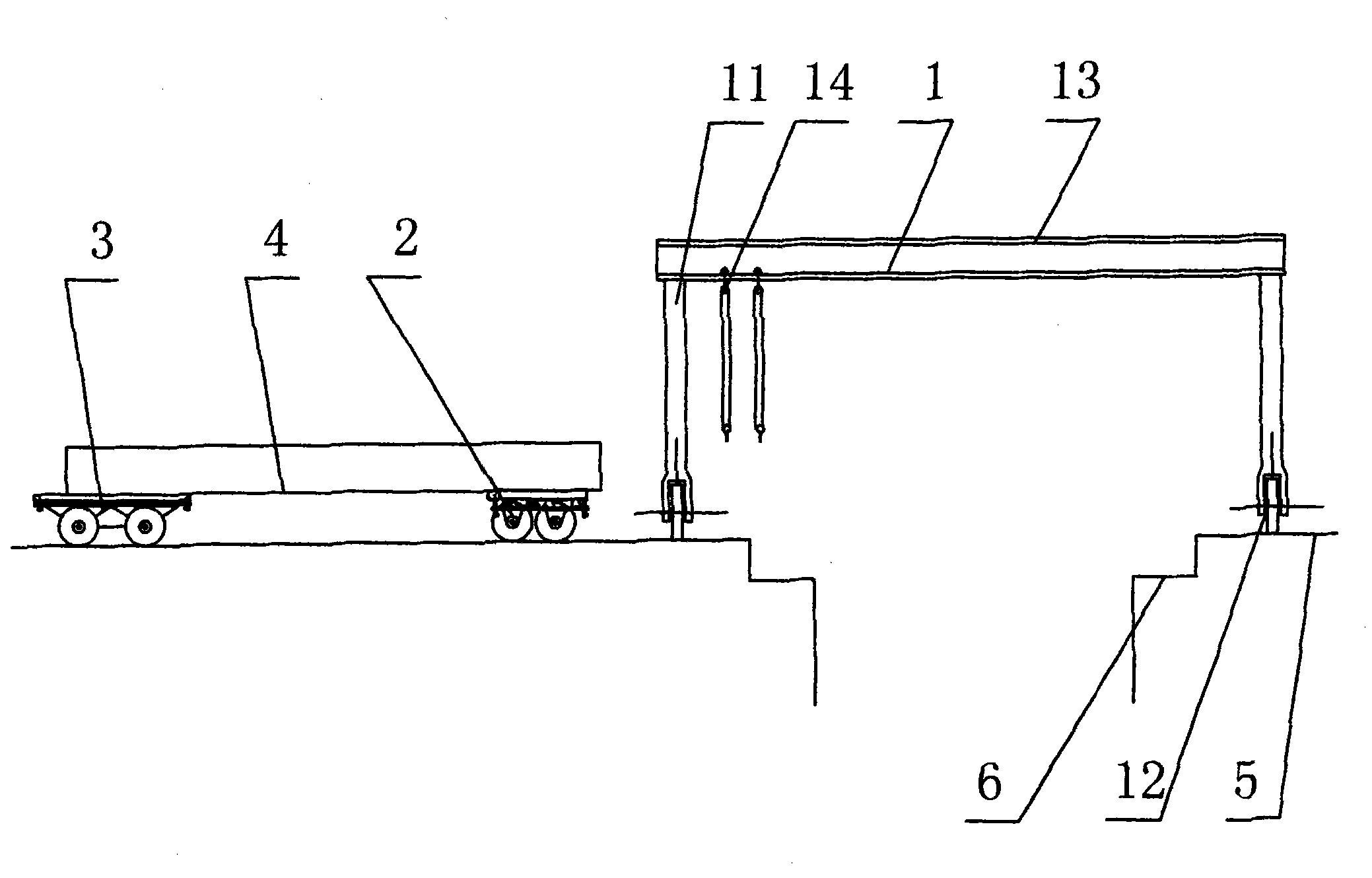
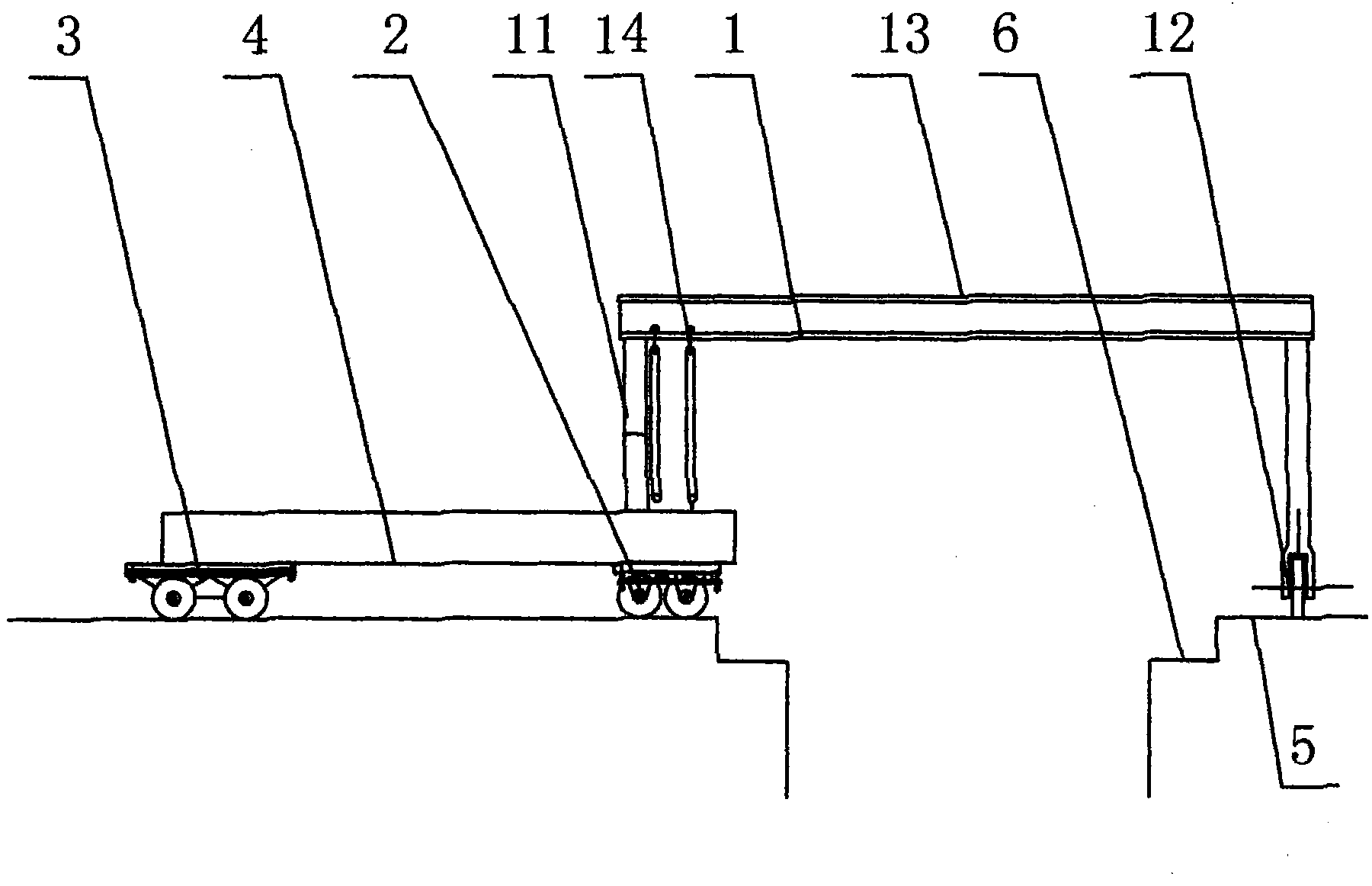
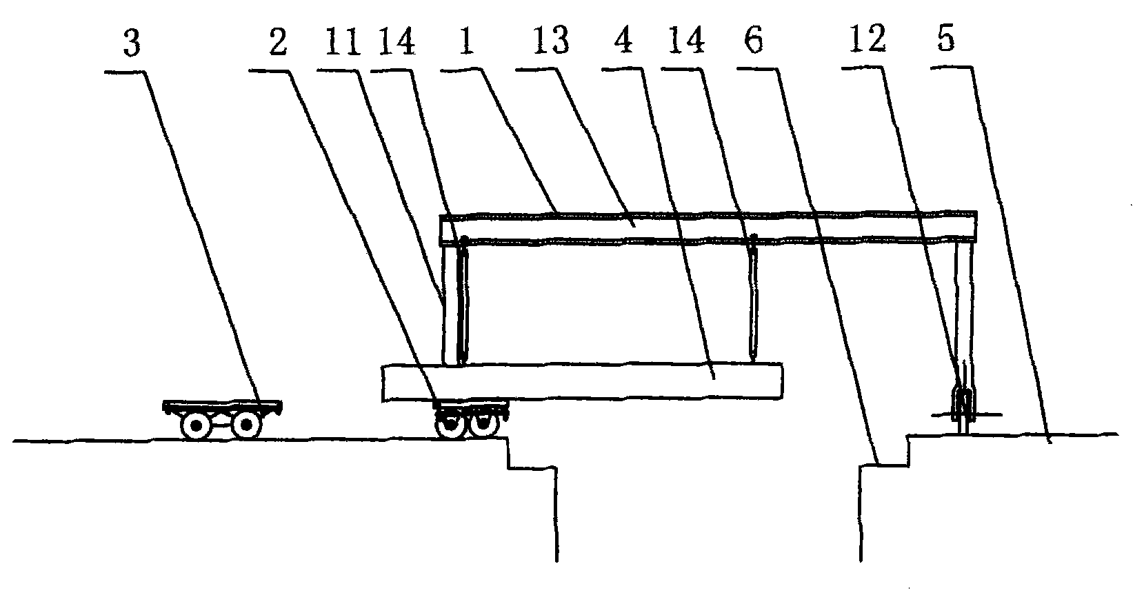
[0030] Example 1, such as figure 1 , figure 2 , image 3 , Figure 4 and Figure 5 Shown: A method for in-situ installation of roof or floor components, which uses a tower crane to hoist the components to the roof or floor, and then hoisting, including the following installation steps:

[0031] A. Support the two ends of the component on the front and rear two trolleys respectively, set a gantry hanger, the gantry hanger spans the two sides of the component installation place, adjust the front and rear two trolleys position, so that the member and the crossbeam of the gantry hanger are on the same vertical plane; as figure 1 As shown, in this embodiment, the front and rear trolleys can be moved manually, or the trolley can be controlled by the power and control system to automatically place the components on the same vertical plane as the crossbeam of the gantry hanger. The beams of the gantry hanger can be selected with different lengths according to the needs, and the ...


PUM


Abstract

The invention provides a method for mounting steel members or prefabricated members of a roof or floor in place and equipment for realizing in-place mounting of the steel members or the prefabricated members of the roof or floor. In the method, the steel members or the prefabricated members (members for short) stacked on the roof or floor are mounted at a position in place; the equipment comprises a gallows frame, a front trolley and a rear trolley, wherein the gallows frame comprises two upright posts, a cross beam and at least two hanging pulleys; the two upright posts are supported against the two ends of the cross beam respectively; the hanging pulleys are hung on the cross beam; the front trolley comprises vehicle wheels, a vehicle body, a movable supporting surface and a roller; the vehicle body is arranged on the vehicle wheels; the movable supporting surface and the roller are arranged on the vehicle body for supporting the members to be mounted; the movable supporting surface is connected with the vehicle body through a lifting mechanism; the roller and the movable supporting surface are flush when positioned at the high position; the rear trolley comprises vehicle wheels, a vehicle body and a movable supporting surface; and the movable supporting surface is connected with the vehicle body through a lifting mechanism. By using some simple machines, the members are stably mounted at the position in place to save time and labor.

Description

technical field [0001] The present invention relates to the installation method and installation equipment of steel components or prefabricated components (hereinafter referred to as components), in particular to an installation method adopted when the components of the roof or floor layer cannot be directly hoisted in place because the vertical transportation equipment cannot cover them and install equipment. Background technique [0002] When installing roof beams or other large prefabricated components, especially some steel components or concrete prefabricated components (hereinafter referred to as components), tower cranes are usually used to hoist the components to the roof floor and stack them loosely. However, generally The tower crane cannot lift and install these components. It can only be transported by manpower using steel pipe rollers to the vicinity where they need to be in place, and then manually installed on the buried plate and rubber pad at the correspondi...

Claims


Application Information

Patent Timeline
IPC IPC(8): E04G21/16
Inventor 肖营沈开权谭锦辰郭宁陈志龙
Owner SHENZHEN CONSTR GRP
Why Eureka
Try Eureka