
Wheel guide rail, car wash system and method for centrally positioning a vehicle

A technology for guiding rails and vehicle cleaning, which is applied in the direction of vehicle cleaning equipment, vehicle cleaning, vehicle maintenance, etc., and can solve problems such as electric shock, vehicle damage and damage to the conversion arm, and achieve the effect of avoiding damage and large measurement windows

Inactive Publication Date: 2011-02-23
WASHTEC HLDG
View PDF7 Cites 9 Cited by
  • Summary
  • Abstract
  • Description
  • Claims
  • Application Information

AI Technical Summary

Problems solved by technology

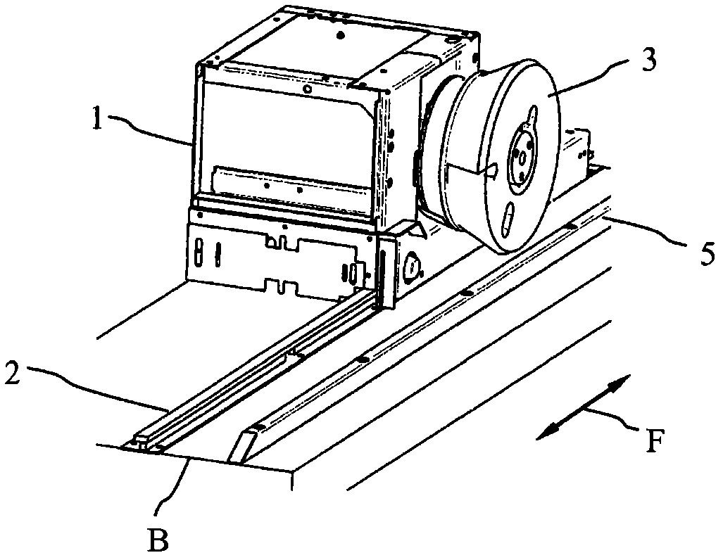
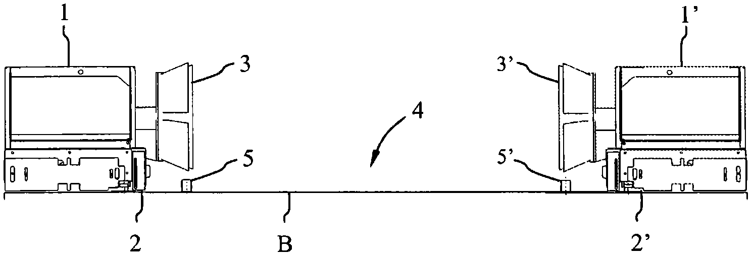
However, this entails the disadvantage that in vehicles with smaller tires or low-profile tires (low-profile tyres), both the rubber tire and the rim itself impinge on the wheel guide rails 5, 5', which usually consist of steel, and are thus damaged
This embodiment has the disadvantage that, due to its mode of operation, the switching arm forcibly protrudes outwards into the range of movement
There is a risk of inadvertent triggering, for example due to objects bending the switching arm in the moving area or due to a short circuit of the open contacts of the switching circuit (tube and switching arm)
There is also the risk of damage to the switching arm by a vehicle that hits or moves past
In addition, there is a risk of electric shock for the operator or user of the device due to open contacts
In addition, no distance measurement is possible, since the switching arm only causes the signal to be switched on or off
The switching arm can only detect whether the vehicle is too close to the wheel guiding track at a certain position on the wheel guiding track, because the triggering of the switching arm triggers the indicator signal, but it cannot determine a specific switching arm from among multiple switching arms that are triggered

Method used


Image

  • Wheel guide rail, car wash system and method for centrally positioning a vehicle
  • Wheel guide rail, car wash system and method for centrally positioning a vehicle
  • Wheel guide rail, car wash system and method for centrally positioning a vehicle

Examples


Embodiment Construction

[0034] Figure 6 to Figure 9 A cross-section of the wheel guide rail according to the invention is shown in the installed state. Wheel guide rails have longitudinal dimensions that match vehicle washing equipment, such as Figure 4 shown in the example. The wheel guide rails according to the invention have fastening means, not shown in the drawings, for example holes in their bottom region, by means of which fastening means these wheel guide rails can be screwed to the bottom of the cleaning device. The direction of movement F of the vehicle to be cleaned in the vehicle washing facility is perpendicular to Figure 6 to Figure 9 the drawing plane.

[0035] The wheel guide track 9 is in the Image 6 The embodiment according to the invention shown in includes an elongated hollow profile made of a stable material, here steel. The bottom 9a and the end side 9b are coplanar and substantially parallel to the bottom B of the washing device.

[0036] The wheel guide side wall 9c ...


PUM


Abstract

The invention relates to a wheel guide rail (9; 10; 13; 14) for a car wash system for laterally delimiting a travel range (4) of a vehicle to be treated in the car wash system and a car wash system comprising treatment devices (1, 1', 3, 3') that can travel along a direction of travel (F) for a vehicle to be treated, a pair of wheel guide rails (10, 10') disposed at the wash system floor (B) between the treatment devices (1, 1', 3, 3') and running in the direction of travel (F) and at a distance from one another perpendicular to the direction of travel (F), said guide rails delimiting a lateral travel range (4) for the vehicle. The object of facilitating a safe and damage-free treatment and cleaning of vehicles is met by the invention by a wheel guide rail, wherein at least one distance sensor (9f; 11; 13f; 14f) is provided in the guide rail (9; 10; 13; 14) for measuring the distance from the guide rail (9; 10; 13; 14) to an outside of the wheel and / or side of the vehicle, a car wash system comprising such wheel guide rails and a method for centrally positioning a vehicle within a vehicle range (4) of a car wash system.

Description

technical field [0001] The invention relates to a wheel guide rail according to the preamble of claim 1 , a vehicle washing device according to the preamble of claim 10 , and a vehicle cleaning device for use in a moving area of ​​a vehicle washing device according to the preamble of claim 12 A method for centering a vehicle. Background technique [0002] The wheel guide track mentioned at the outset is known from DE 21 04 049 A. In particular for washing plants, the traction device for the vehicle has two guide rails between which the wheels on the sides of the vehicle move. The guide rail has a flat web arranged substantially perpendicularly to the bottom of the vehicle washer, on the upper end of which a longitudinal bar with a circular cross section is arranged. [0003] Figure 1 to Figure 5 Further wheel guide rails of the described type for vehicle washing installations are shown. 1 shows the left side support foot 1 of the mast column (not shown) of the movable wa...

Claims


Application Information

Patent Timeline
Patent Type & Authority Applications(China)
IPC IPC(8): B60S3/00
CPCB60S3/042B60S3/004
Inventor G·维默尔
Owner WASHTEC HLDG
Learn More