Road and obstacle detecting method based on remotely piloted vehicles

A technology for obstacle detection and unmanned vehicles, which is applied in image data processing, instruments, character and pattern recognition, etc. It can solve problems such as poor robustness of roadside detection, lack of slope detection, and difficulty in fusion of front and rear frames

Inactive Publication Date: 2015-05-20
BEIJING UNIV OF TECH
View PDF3 Cites 74 Cited by
  • Summary
  • Abstract
  • Description
  • Claims
  • Application Information

AI Technical Summary

Problems solved by technology

[0006] Aiming at the problems existing in the prior art, such as lack of road slope detection, poor robustness of road edge detection, and difficulties in front and rear frame fusion, the present invention proposes a road and obstacle detection method in unmanned vehicles, using four-line laser radar as The distance sensor calculates the slope information of the road in the drivable area according to the relative positional relationship of the road surface data points on different scanning layers of the lidar; according to the characteristics of the data points along the road, the improved COBWEB algorithm and the least square method based on the Euclidean distance Fitting the left and right road edges, enhancing the anti-interference ability, accuracy and stability of road edge detection; applying DST evidence theory (Dempster-Shafer theory) to establish a grid map for the environment in front of the unmanned vehicle, and frame the map before and after fusion Before, the position estimation of each grid is performed first, so that the grid fusion problem of the front and rear frames is solved in the local map; finally, the conflict coefficient is used to detect dynamic obstacles in the drivable area, and the dynamic obstacle is detected by improving the eight-neighborhood area marking algorithm. Obstacles for clustering and information extraction

Method used


Image

  • Road and obstacle detecting method based on remotely piloted vehicles
  • Road and obstacle detecting method based on remotely piloted vehicles
  • Road and obstacle detecting method based on remotely piloted vehicles

Examples


Embodiment Construction

[0059] The present invention will be further described below in conjunction with the accompanying drawings and embodiments.

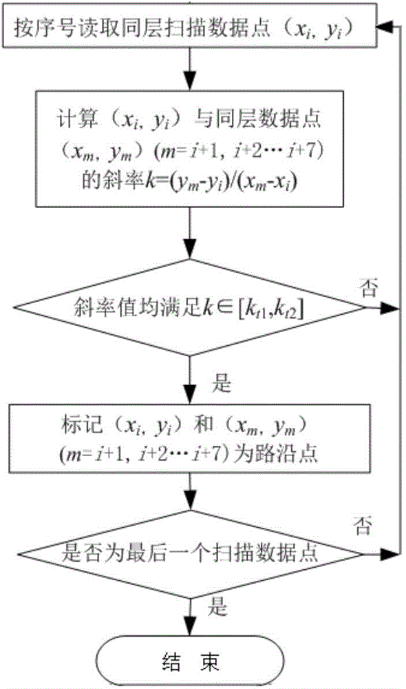
[0060] In this embodiment, the IBEO-LUX 2010 four-line laser radar is selected as the main sensor, combined with the vehicle camera, odometer and other sensors, and the algorithm is written in the VS2010 environment to realize a road and obstacle detection method in an unmanned vehicle. Specific implementation methods such as Figure 6 shown, including the following steps:

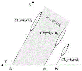
[0061] Step 1, see attached figure 1 According to the characteristics of data points along the road, the roadside data set is extracted from numerous lidar data.

[0062] Through experimental analysis of the difference between the data points scanned onto the roadside and other radar data points, it is concluded that the data points along the roadside have the following attributes: when the laser radar is scanned onto the roadside, the returned data points show stability in the sa...


PUM


Abstract

The invention relates to a road and obstacle detecting method based on remotely piloted vehicles. The method includes adopting a four-wire laser radar as a distance sensor and calculating slope information of roads in a driving area according to the relative position correspondence of pavement data points on different scanning layers; fitting left and right road edges by the COBWEB algorithm and the least square fit improved on the basis of Euclidean distance according to characteristics of road edge data points, enhancing anti-jamming capability, accuracy and stability of road edge detection; applying DST (Dempster-Shafer theory) evidence theory to establish a raster map for the environment ahead of the remotely piloted vehicles, and estimating positions of each raster before integrating prior- and posterior-frame maps. Consequently, the problem of integration of prior and posterior raster cells in the local map is solved. Finally, dynamic faults can be detected by means of conflict coefficient in a driving area, and the dynamical obstacles can be clustered and information thereof can be extracted by the improved eight-neighborhood zone marker algorithm. The road and obstacle detecting method can stably and accurately detect road and obstacle information.

Description

technical field [0001] The invention belongs to the field of driverless vehicles, and in particular relates to a road and obstacle detection method based on driverless vehicles. Background technique [0002] Unmanned vehicles are an important part of intelligent transportation systems. Unmanned vehicles driving in urban environments need to have good perception of the surrounding environment, including the perception of road structures and the detection of other dynamic obstacles. Reliable situational awareness plays a vital role in autonomous cruise control, collision warning and path planning. [0003] Usually, unmanned vehicles can carry and install sensors with environmental perception functions such as cameras, radars, and GPS. Among them, lidar has excellent characteristics such as not being affected by weather, lighting and other factors, not relying on texture and color to distinguish, and not sensitive to shadow noise. In addition, lidar has high scanning frequenc...

Claims


Application Information

Patent Timeline
Patent Type & Authority Applications(China)
IPC IPC(8): G06K9/66G06T7/00
Inventor 段建民郑凯华
Owner BEIJING UNIV OF TECH
Why Eureka
Try Eureka