Bladeless fan

A bladeless fan and fan technology, applied in non-variable-capacity pumps, pump devices, machines/engines, etc., can solve the problems of unstable placement and use, easy toppling, etc., and achieve a simple and beautiful device structure, stable use, and reduced The effect of vibration or noise

Inactive Publication Date: 2011-03-16
任文华
View PDF6 Cites 110 Cited by
  • Summary
  • Abstract
  • Description
  • Claims
  • Application Information

AI Technical Summary

Problems solved by technology

Due to the large nozzle and small base of this kind of fan, it is not stable to place and use, and it is easy to fall ov

Method used


Image

  • Bladeless fan
  • Bladeless fan
  • Bladeless fan

Examples


Embodiment Construction

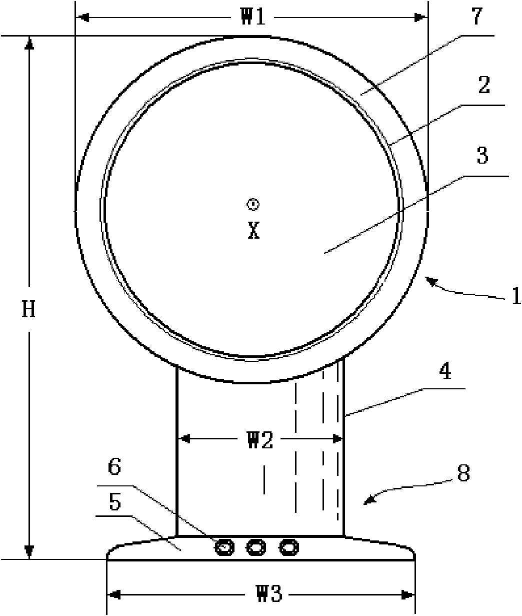
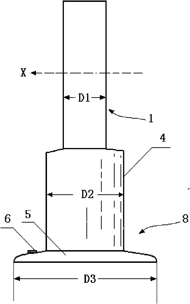
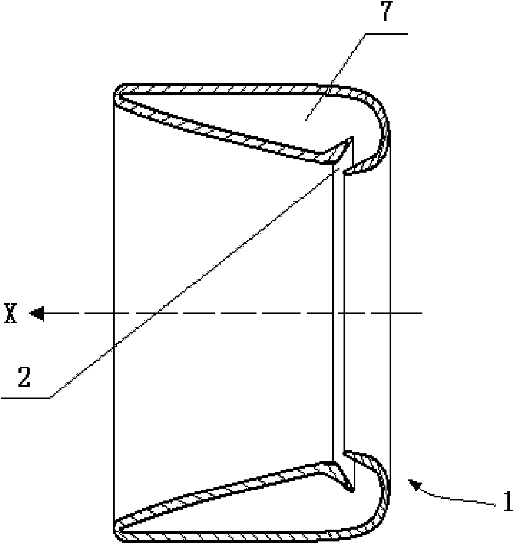
[0023] figure 1 It is a schematic diagram of the bladeless fan of the present invention. As can be seen from the figure, the device of the present invention includes: a base 8 and a nozzle 1 installed on the base, the nozzle includes an internal channel 7 and an exhaust port 2, and the air flow is injected through the exhaust port 2, and the nozzle 1 is about the axis X Extending substantially orthogonally to define the opening 3, the air outside the fan is sucked by the air flow ejected from the exhaust port 2 through the opening 3, the base 8 includes a base 5 and a support 4 fixed on the base, the nozzle 1 is installed on the support 4, a motor and an impeller (not shown in the figure) are arranged in the support 4, and the fan has a height H and a width perpendicular to the height, and the height and the width are vertical on axis X. In this embodiment, the cross-section of the nozzle 1 is generally circular, the opening 3 is also generally circular, the support 4 is gen...


PUM


Abstract

The invention discloses a bladeless fan, and relates to a fan device. The fan device comprises a base and a nozzle arranged on the base, wherein the nozzle comprises an internal channel and an air outlet; the nozzle basically extends orthogonally relative to an axis to limit an opening; and air outside the fan is sucked by airflow jetted from the air outlet through the opening. The fan device is characterized in that: the base comprises a pedestal and a support fixed on the pedestal; the nozzle is arranged on the support; the fan has a height and a width which are vertical to the axis; the width of the support of the fan is at least 10 millimeters less than that of the pedestal; the width of the pedestal of the fan is greater than 75 percent of the width of the nozzle and smaller than 125 percent of the width of the nozzle; and selectively, the nozzle, the pedestal and the support have depths along the direction of the axis, the depth of the support is at least 10 millimeters less than that of the pedestal, the depth of the pedestal is greater than 200 percent of the depth of the nozzle and smaller than 350 percent of the depth of the nozzle. The fan device can be safely and stably placed and used and has a simple and attractive structure.

Description

technical field [0001] The invention relates to a fan device. Background technique [0002] The Chinese patent application with publication number CN 101424278A (application number: 200810177843.3) published on May 6, 2009 discloses a bladeless fan for generating air flow. The nozzle, the base is provided with a member for generating the air flow through the nozzle, the nozzle has an internal channel for receiving the air flow from the base and an exhaust port, the air flow is injected through the exhaust port, the nozzle is about The axis extends substantially orthogonally to define an opening through which air external to the fan is drawn by the airflow jetted from the exhaust port. Because the nozzle of this kind of fan is relatively large and the base is small, its placement and use are not stable, and it is easy to topple over, especially when operating the fan control button arranged on the side wall of the base, so it is necessary to improve it. Contents of the inv...

Claims


Application Information

Patent Timeline
IPC IPC(8): F04F5/16F04F5/46
CPCF04D25/08F04F5/16F04F5/46
Inventor 任文华
Owner 任文华
Why Eureka
Try Eureka