Hot bulge forming apparatus, a hot bulge forming method and a product formed through hot bulge forming

A technology of formed products and thermal expansion, applied in the direction of forming tools, metal processing equipment, manufacturing tools, etc., can solve the problems of shrinkage of workpieces, reduction of pushing force, etc.

Inactive Publication Date: 2011-03-23
HONDA MOTOR CO LTD
View PDF5 Cites 6 Cited by
  • Summary
  • Abstract
  • Description
  • Claims
  • Application Information

AI Technical Summary

Problems solved by technology

[0005] However, since the force pushing the inside of the workpiece decreases once the internal pressure is released, the workpiece shrinks to a large extent

Method used


Image

  • Hot bulge forming apparatus, a hot bulge forming method and a product formed through hot bulge forming
  • Hot bulge forming apparatus, a hot bulge forming method and a product formed through hot bulge forming
  • Hot bulge forming apparatus, a hot bulge forming method and a product formed through hot bulge forming

Examples


Embodiment Construction

[0039] Hereinafter, one embodiment of the present invention will be described with reference to the drawings.

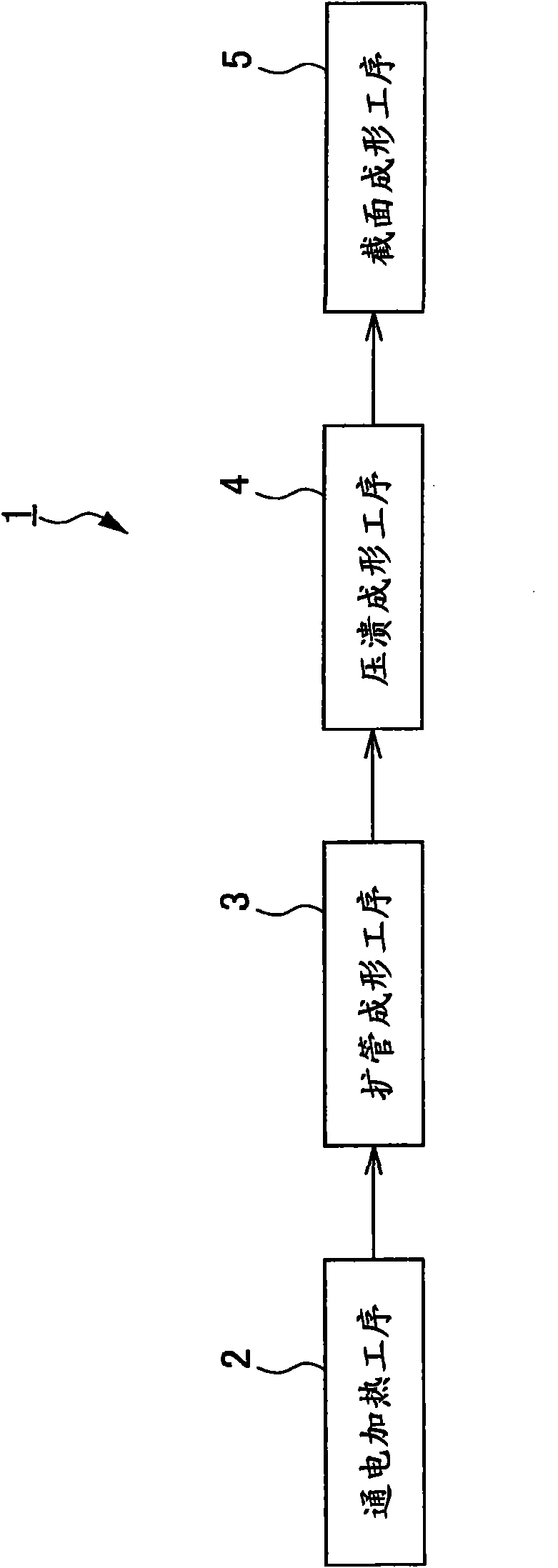
[0040] figure 1 It is a flowchart showing the operation of the thermal expansion molding device 1 according to one embodiment of the present invention.

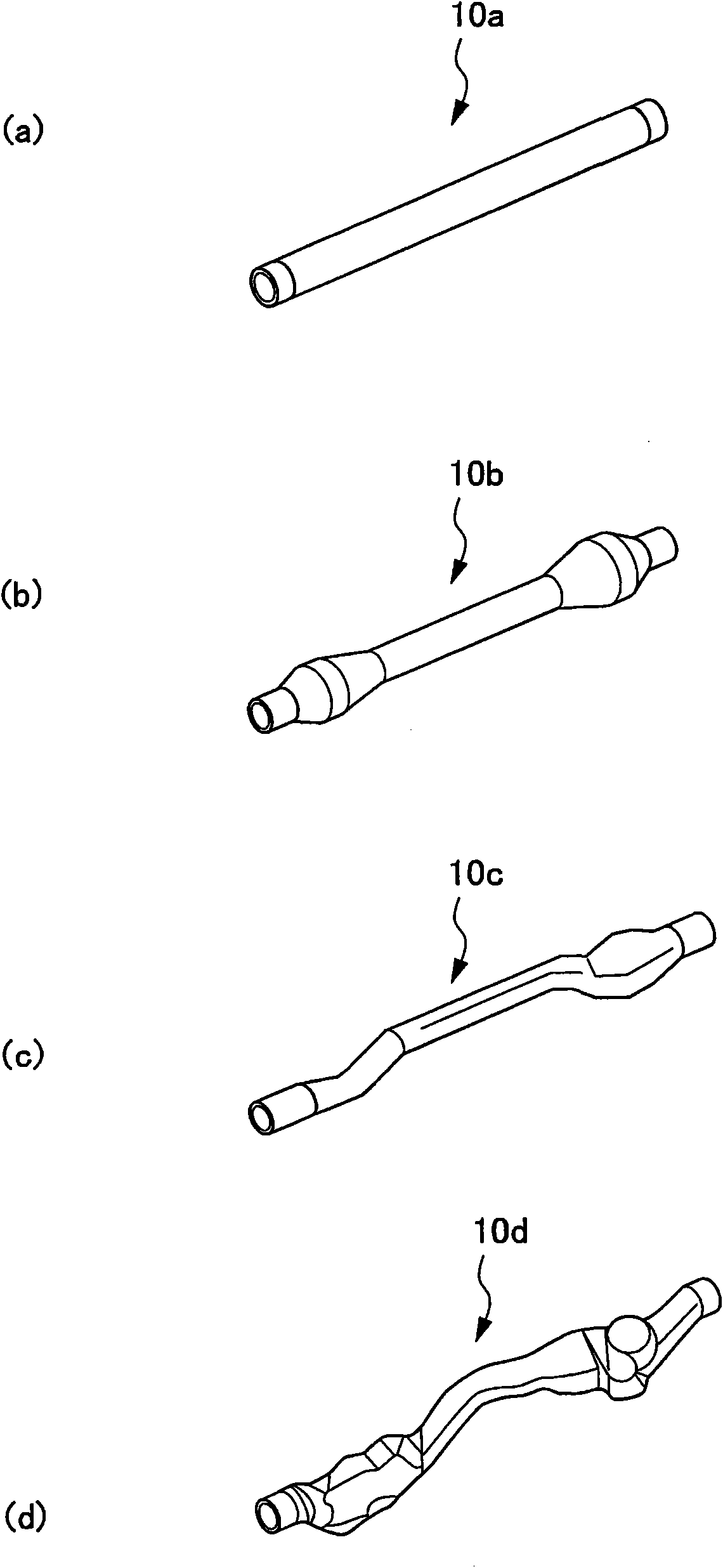
[0041] figure 2 It is a perspective view showing tubular blanks 10 a to 10 d which are workpieces formed by the thermal expansion molding apparatus 1 .

[0042] The thermal expansion forming device 1 performs the following steps in the following order: energized heating step 2, tube expansion forming step 3 as a preliminary forming step, crush forming step 4, and cross-section forming step 5 as a final forming step.

[0043] Specifically, in the energization heating step 2, the tubular blank 10a made of an aluminum alloy extending substantially linearly is heated.

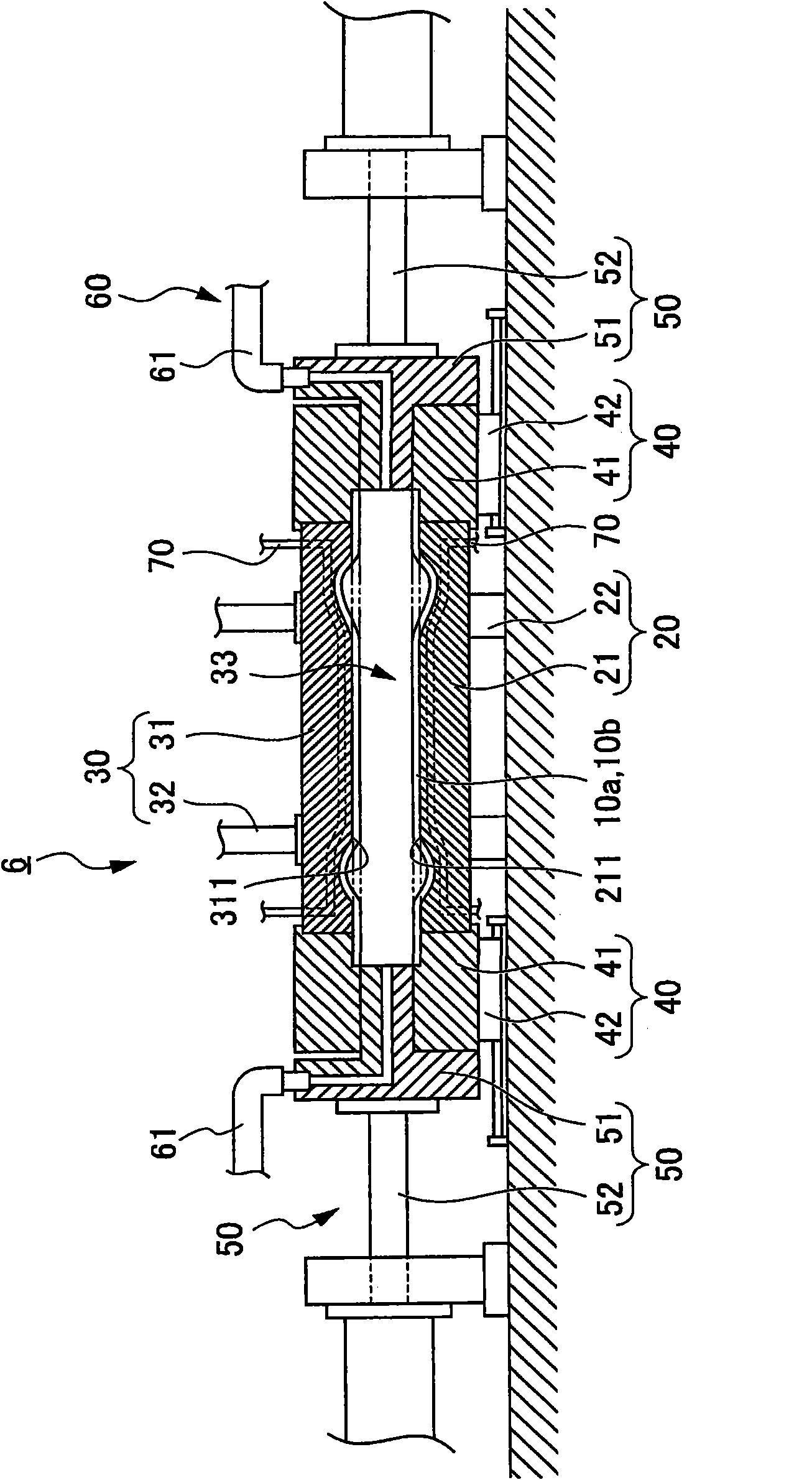
[0044] In the pipe expansion forming step 3, the first expansion forming device 6 (refer to image 3 ), expand the portions near both ends of the ...


PUM


Abstract

The present invention relates to a hot bulge forming apparatus, a hot bulge forming method and a product formed through hot bulge forming, which can suppress a generation of a dent at a lengthwise central side of a workpiece. In the hot bulge forming apparatus 1, a preheated tubular material 10b is disposed in a cavity 33A defined by dies 21A, 31A, air is supplied into an interior of the tubular material 10b so that the tubular material 10b is pressed against cavity surfaces 211A, 311A by the pressure of the air to thereby form the tubular material 10b into a shape defined by the cavity 33A. Thereafter, the resulting tubular material 10c is disposed in a cavity 33B defined by dies 21B, 31B, and air is supplied into an interior of the tubular material 10c so that the tubular material 10c is pressed against cavity surfaces 211B, 311B by the pressure of the air to thereby form the tubular material 10c into a shape defined by the cavity 33B while the tubular material 10c is cooled by the cavity surfaces 211B, 311B. Projecting portions 331 each having an arc-shaped section are formed at portions of the cavity surfaces 211A, 311A against which lengthwise end sides of the tubular material 10b are pressed.

Description

technical field [0001] The invention relates to a thermal expansion forming device, a thermal expansion forming method and a thermal expansion forming product. Specifically, it relates to a thermal expansion forming device, a thermal expansion forming method, and a thermal expansion molding product in which a preheated tubular workpiece is placed in a cavity of a metal film, a fluid is supplied to the cavity, and the fluid The pressure pushes the workpiece against the cavity surface of the metal film to form it, and then the formed workpiece is cooled by the metal film. Background technique [0002] Conventionally, thermal expansion forming is known in which high-pressure air is supplied to a cavity of a metal film to form a tubular workpiece. [0003] Specifically, in the thermal expansion forming, for example, a tubular workpiece is heated in advance, and the tubular workpiece is placed between a pair of metal films. Next, the metal film is laminated while restraining bo...

Claims


Application Information

Patent Timeline
Patent Type & Authority Applications(China)
IPC IPC(8): B21D26/033B21D37/10B21D53/00
CPCB21D26/041B21D37/16B21D26/033
Inventor 山本大介石原好光狩野贵之
Owner HONDA MOTOR CO LTD
Why Eureka
Try Eureka