Electrical connector assembly with detachable pivot shaft and pivot hub with insert

a technology of electric connectors and pivot shafts, which is applied in the direction of connection contact members, contact members penetrating/cutting insulation/cable strands, coupling device connections, etc., can solve the problems of limiting the ability of connectors to effectively pierce insulated, low voltage connectors in the prior, and inability to hold and pierce better quality low voltage cables, etc., to achieve accurate and easy penetration of conductor wires

Inactive Publication Date: 2015-11-26
BARTELL JACK R
View PDF0 Cites 5 Cited by
  • Summary
  • Abstract
  • Description
  • Claims
  • Application Information

AI Technical Summary

Benefits of technology

[0010]It is an object of the present invention to provide a low voltage cable connector that has sturdy metal conductor pins capable of piercing the insulated sheathings of a source conductor and a fixture conductor of a quality gauge and thickness, with limited damage to both the source and fixture conductors upon penetration of their stranded wires.
[0011]It is a further object of the present invention to provide a low voltage cable connector that enables a water tight connection between insulated direct burial wire (DBR) pairs of varying gauges without the need to remove, cut, or strip the insulation, from either the fixture or source conductors.
[0012]The exemplary embodiment of the cable connector of the present invention, has a uniquely shaped design having a detachable base pivot hub and a top pivot shaft that can be separated completely into their respective parts and further allows them to engage and disengage an unlimited number of times. In this embodiment, the connector assembly connects two sides of a source conductor to the corresponding two fixture conductors. Further in this embodiment of the invention, the metal conductor pins used to penetrate the source and fixture conductors have a special arc design to enable accurate and easy penetration of the conductor wires. In addition, the specially designed ridges on the top and base parts of the connector assembly create a water tight seal with the source conductor insulation sheath when they are fully closed. Further in this embodiment of the invention, the interlocking guide posts in the base part and the slots in the top part fully align the metal conductor pins with the center of the source conductor and the corresponding fixture conductor as the assembly is rotated ninety degrees from the open position to the fully closed position. These interlocking posts and slots engage with sufficient friction to prevent the assembly from recoiling open and will further retain the assembly in the fully closed position in the absence of an external force which may cause the assembly to open partially or completely. In addition, the embodiments of the connector assembly have a unique shape which presents the smallest circumference of the closed assembly such that it can be permanently secured with a variety of closure devices without the possibility of the closure device sliding out of position unless it is loosened or completely detached. Such closure devices include, but are not limited to, custom designed plastic, metallic, or nylon accessories, or readily available commercial devices such as zip ties, clips, wires, tapes, and clamps.
[0013]In the exemplary embodiment of the cable connector of the present invention, the design of the connector assembly provides separate conductor wire channels which hold the wires securely in place and allow for the precise vertical penetration of the conductor pins through the source conductor and the fixture conductors. This embodiment of the cable connector of the invention, allows the use of a 12 American Wire Gauge (12 AWG) source conductor and 18 American Wire Gauge (18 AWG) fixture conductors.
[0015]In yet another exemplary embodiment of the invention, the base pivot hub section of the connector assembly is modified to include only the source conductor wire channel. In this embodiment of the invention, the fixture conductor wire channels form part of an insert device which is form fitted to interlock with the base pivot hub section. The two fixture conductor wire channels configured with the insert device are designed to support 16 AWG and 18 AWG fixture conductor wires. In this embodiment, the fixture conductor wires are threaded through the fixture conductor wire channels in the insert device before the insert device is locked into the base pivot hub section. In this embodiment, when the top pivot shaft section is interlocked with the base pivot hub section, the metal conductor pins on the top pivot shaft section first penetrate the fixture conductor wires placed within the fixture conductor wire channels in the insert device before penetrating the source conductor wire held in the source conductor wire channel in the base pivot hub section. In this embodiment of the invention, the metal conductor pins are not bent into an arc shape as in the previous embodiment where the pins have to penetrate into the thicker source conductor wire first before penetrating the smaller fixture conductor wires. Rather, the metal conductor pins in this embodiment have a straight shape since they will be penetrating the smaller fixture conductor wires first before penetrating the source conductor wire. The use of the insert device configured with the fixture conductor wire channels eliminates the need for fixture conductor wire channels to be molded to the base pivot hub section.

Problems solved by technology

Many of the popular brands of low voltage connectors available in the market today have significant deficiencies in their construction and operation.
For example, in one of the popular brands of the low voltage connectors in the market, the metal conductor spikes used to establish the contact with the wiring within the cables is reported to have a tendency to bend, thereby limiting the connector's capability to effectively pierce the insulated sheathing of the cables to electrically connect the source conductor and the fixture conductor.
Many of the most popular low voltage connectors are prone to misalignment of the metal conductor element, which prevents the conductor from making contact with the current-carrying inner metal strands of the target conductor wire.
The other limiting feature of some of the low voltage connectors in the prior art are their incapacity to hold and pierce the better quality low voltage cables with a thicker insulating sheathing.
A major drawback of the low voltage connectors in the prior art is in their inability to protect the connection from excessive moisture and oxygen which causes corrosion and ultimately failure of the electrical connection.
Some of the low voltage connectors used for outdoor lighting and other tasks are also known to be constructed of poor quality plastic that can melt or turn brittle from prolonged exposure to the elements.

Method used


Image

  • Electrical connector assembly with detachable pivot shaft and pivot hub with insert
  • Electrical connector assembly with detachable pivot shaft and pivot hub with insert
  • Electrical connector assembly with detachable pivot shaft and pivot hub with insert

Examples


Embodiment Construction

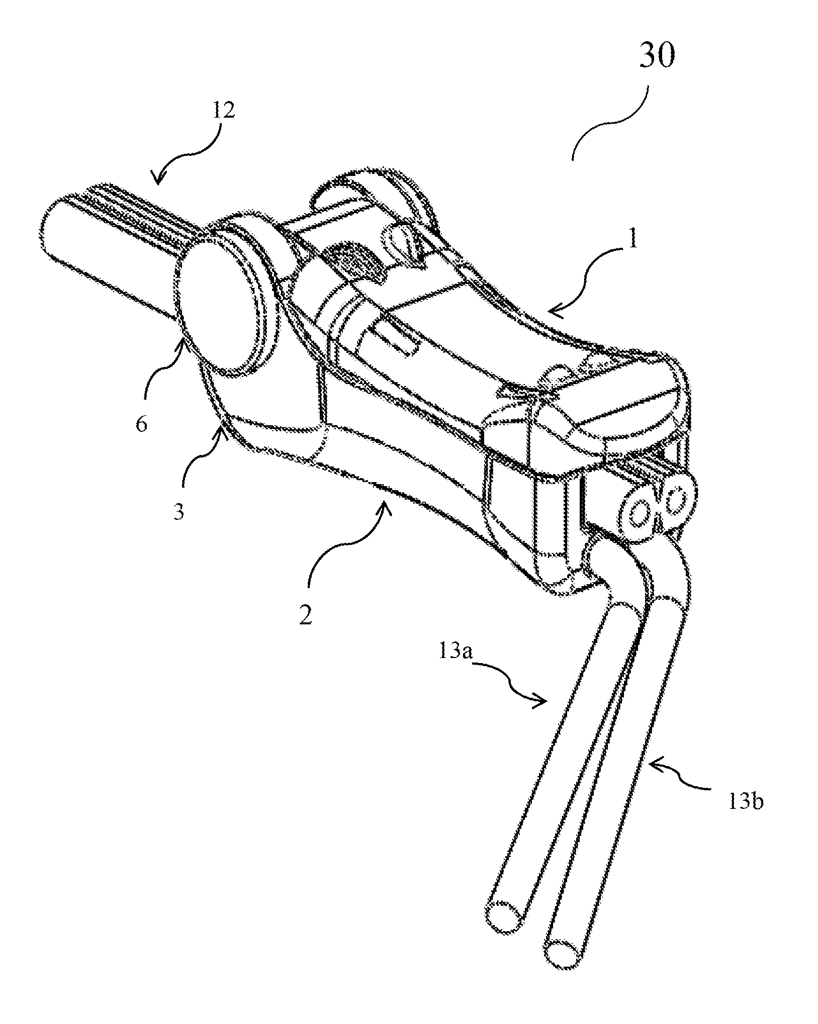
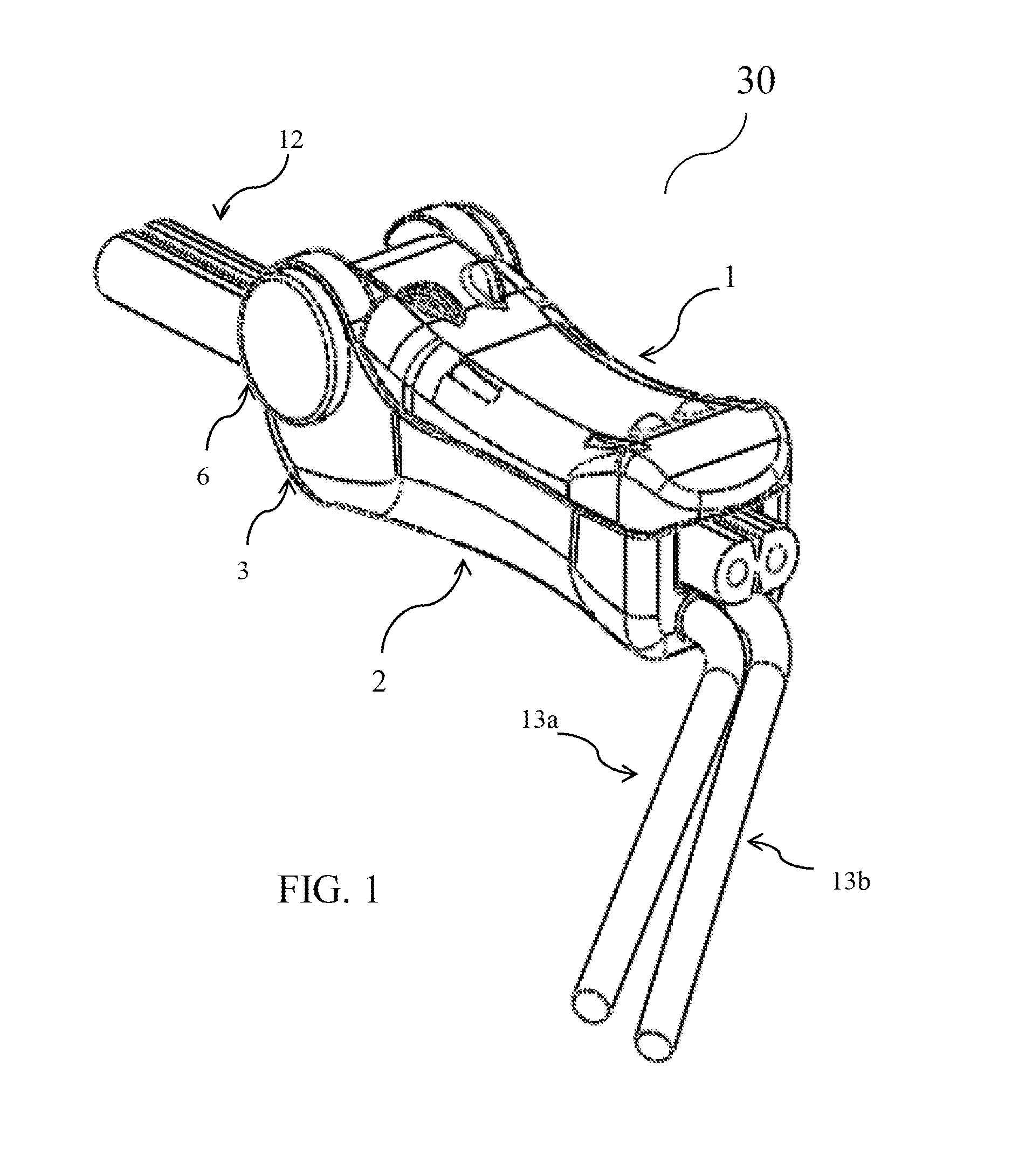
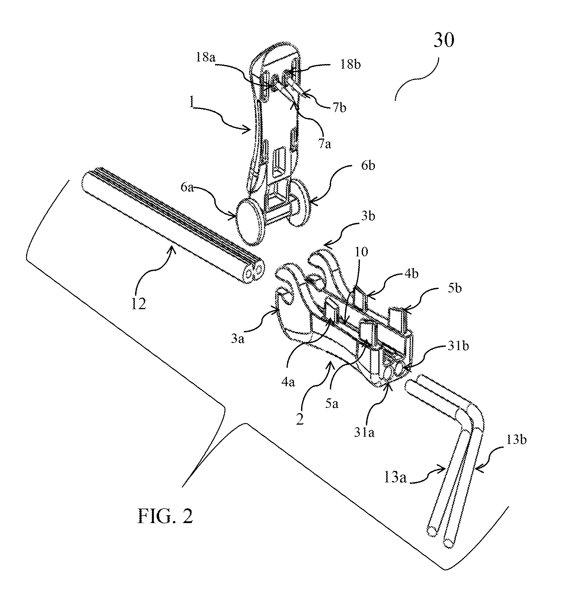
[0045]The present invention is a cable connector assembly with a detachable pivot shaft and pivot hub to connect the primary 0v-49v DC direct burial source conductor (DBR) to fixture conductors used in outdoor lighting and irrigation systems. The exemplary embodiment of the invention has fixture conductor channels molded into the base pivot hub section of the connector assembly. In yet another exemplary embodiment of the invention, an insert device is configured with the fixture conductor wire channels to hold the fixture conductor wires on the base pivot hub section above the source conductor wire held in the source conductor wire channel at the bottom of the base pivot hub section of the connector assembly.

[0046]Referring now to the drawings, more particularly to FIG. 1 a perspective view of the exemplary embodiment of the cable connector 30 of the present invention is shown having a unique alligator design. In this embodiment of the cable connector 30 shown in the closed configur...


PUM


Abstract

An electrical cable connector assembly comprising a top pivot shaft and a base pivot hub having an insert with fixture conductor channels form fitted on the base pivot hub to hold the fixture conductor wires. The top pivot shaft interlocks with the base pivot hub at one end and upon rotation at ninety degrees the connector assembly is closed completely. Upon closure with nominal hand force, a pair of metal conductor pins molded to the top inside end of the top pivot shaft easily penetrates the fixture conductor wires held in the insert and the source conductor wire held in the source conductor wire channel in the base pivot hub, to connect the two sets of conductors electrically. The small diameter of circumference at the mid section of the uniquely designed cable connector allows for the use of an optional closure to secure the cable connector in place.

Description

CROSS REFERENCE TO RELATED APPLICATION[0001]This is a continuation-in-part application of U.S. patent application Ser. No. 14 / 021,398 filed on Sep. 9, 2013.FIELD OF THE INVENTION[0002]This invention is generally related to low voltage connectors. More particularly, the present invention is related to a connector assembly with a detachable pivot shaft and pivot hub to electrically connect fixture conductors with a source conductor using metal conductor pins.BACKGROUND OF THE INVENTION[0003]Electrical cable connectors in general are well known in the art. In the past, electrical contact between cable conducting wires was normally achieved through soldering, crimping or insulation displacement of the cables. More recently, these methods have been replaced by the penetration method which comprises the use of metal conductors in the shape of spikes, or lances to pierce the insulation sheath of the cable conductors to facilitate electrical contact between the wires, thus obviating the nee...

Claims


Application Information

Patent Timeline
Patent Type & Authority Applications(United States)
IPC IPC(8): H01R4/24H01R13/52H01R4/64
CPCH01R4/2404H01R13/5208H01R4/646H01R4/22H01R4/2412
Inventor BARTELL, JACK R.
Owner BARTELL JACK R
Why Eureka
Try Eureka