
Prosthetic heart valve

a heart valve and prosthesis technology, applied in the field of bioprosthetic heart valves, can solve the problems of valve replacement, valve repair, and inability to repair but replace the valve, so as to increase the overall stability of the valve and prolong the service li

Active Publication Date: 2015-10-15
SHANGHAI CINGULAR BIOTECH
View PDF1 Cites 4 Cited by
  • Summary
  • Abstract
  • Description
  • Claims
  • Application Information

AI Technical Summary

Benefits of technology

The present invention provides a prosthetic heart valve with a stent design that ensures a better match between the stent and the alloy wire, making the valve more stable and increasing its service life. The stent consists of at least two layers of ring, with one layer being a ring of higher hardness and one layer being a ring of better elasticity. The inner diameter of the outer ring can be slightly smaller than the outer diameter of the inner ring before assembly, which helps the stent tend to remain annular in both a stationary and stressed state. An additional third stent layer may be added to further enhance the stability of the valve structure.

Problems solved by technology

Therefore, the consequence of dysfunction of the aortic valve and the mitral valve on the left side of the heart is usually more serious than that of the other two valves.
The aortic valve is prone to stenosis due to the accumulation of calcified materials on the leaflets.
In developed countries, common mitral valve cases are caused by the elongation of the chordae tendincae and myocardial ischemia; while in developing countries and gathering areas where the majority of immigrants are from developing countries, common mitral valve cases are caused by rheumatic heart disease, and in such cases, the valve can not be repaired but to be replaced.
The incomplete opening of the valve leads to valvular stenosis and thus obstructing the blood flow, while the incomplete closure of the valve results in the back flow of the blood.
Both of the conditions increase the burden on the heart, and the situation is not optimistic.
The more serious the situation is, the greater the impact is on the patient.
If untreated, both of the conditions will lead to gradual heart failure and result in death of the patient finally.
Congenital or acquired heart disease will cause anatomical or functional abnormalities of heart valves which threatening the life of a patient.
However, in practice, many dysfunctional valves can not be treated through repair.
For instance, a patient suffering from rheumatic heart disease is not suitable for mitral valve repair.
While the use of too much anticoagulant may increase the risk of bleeding and this is very disadvantageous to the patients.
In addition, the noise of a working mechanical valve is relatively big, and the mechanical valve may suddenly fail to work without any warning, and incarceration or prolapse may occur to the leaflets, causing serious consequences, even death of the patient.
However, with the passage of time, some natural processes in the human body may gradually make the bioprosthetic leaflets become stiff or calcified, particularly the high-stress areas of the leaflets, such as the junctions between the leaflets and the surrounding attachment points of the leaflets or the ‘cusps’ at the outer edge of each leaflet.
So the bioprosthetic valve will eventually be worn out and still need to be replaced by a new one.
Because the bioprosthetic valves are generally handmade and are made by specially trained and skilled personnel, it is very time-consuming and is more difficult than producing mechanical valves.
Even after decades of continuous improvement, the existing bioprosthetic valves still have some drawbacks.
One of the drawbacks is the low matching degree between the alloy wire and the stent, which is often due to the deformation of the ring structure.
This producing process makes the stent susceptible to spring-back effect of the material and undergo deformation.
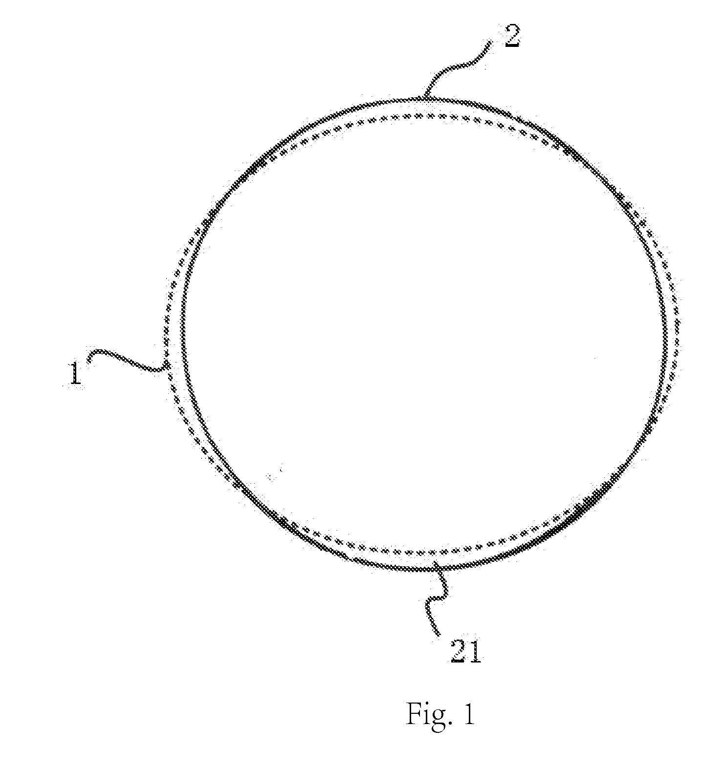
The stress applied to the stent upon sewing it together with the alloy wire, and that experienced during normal functioning of the valve, makes the stent further susceptible to deformation, resulting in dislocation between the alloy wire and the stent. FIG. 1 shows the mismatch existing between the circular alloy wire 2 and the annular stent 1.
This mismatch often leads to a shift of the alloy wire from the stent, which reduces the stability of the entire valve, and thus resulting in uneven stress on the valve, especially on the valve leaflets, which leads to wrinkles, expedites wearing of the valve and reduces the service life.

Method used


Image

  • Prosthetic heart valve
  • Prosthetic heart valve
  • Prosthetic heart valve

Examples


first embodiment

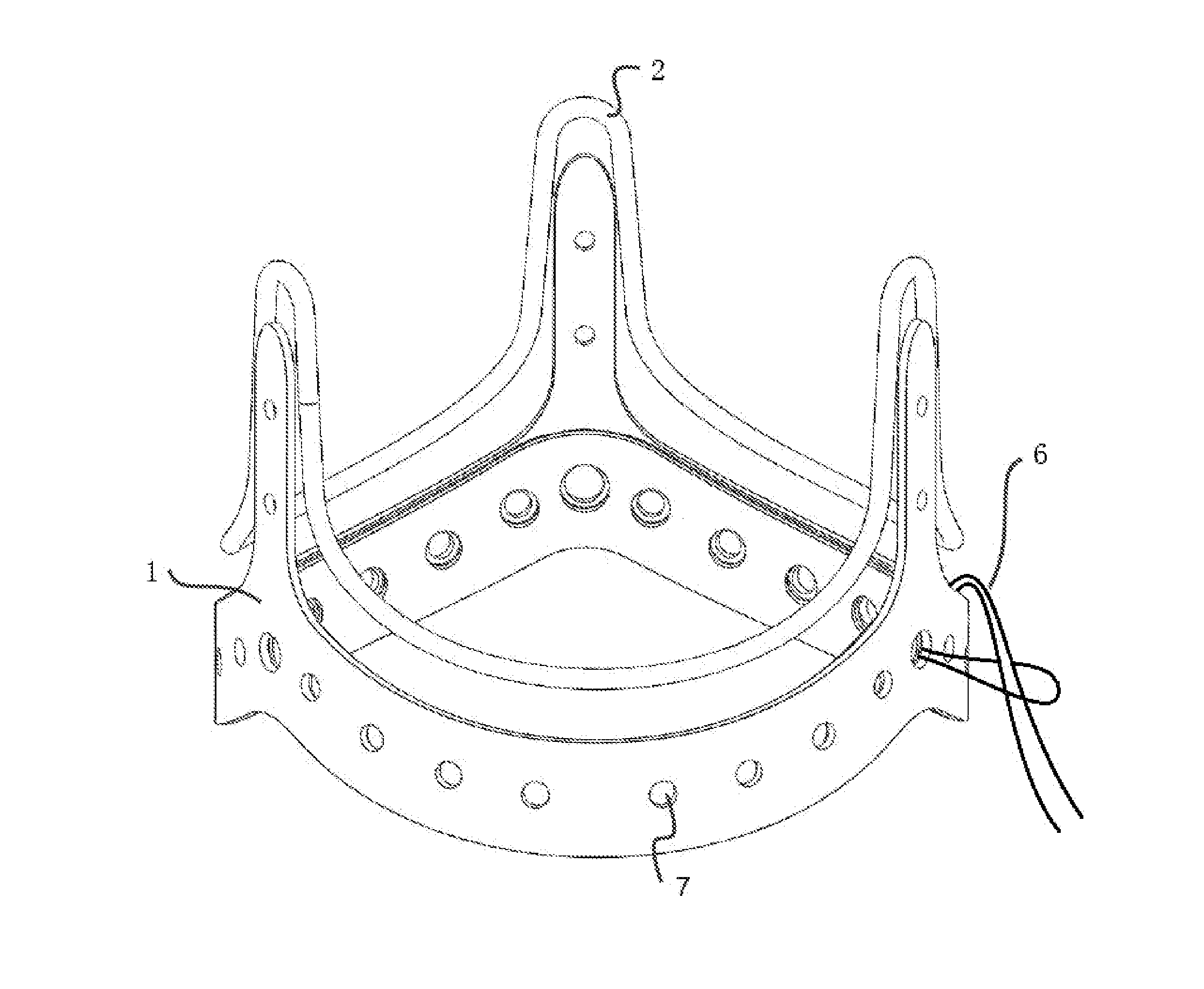
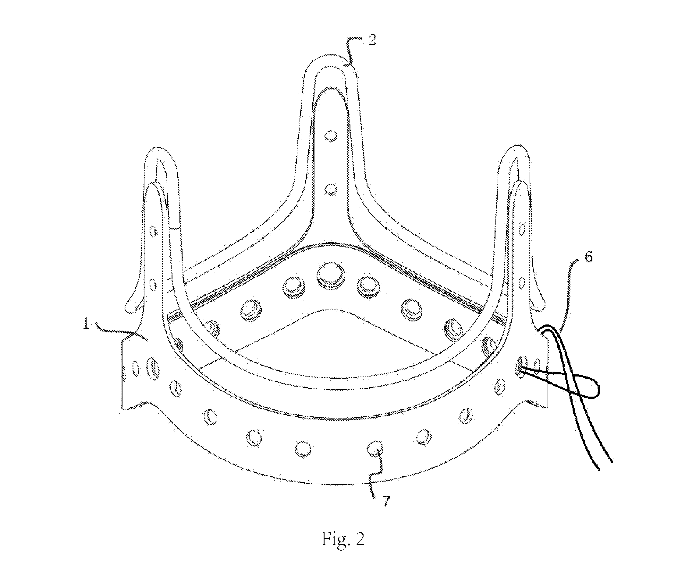
[0027]FIG. 2 and FIG. 3 show the prosthetic heart valve provided by the present invention. As shown in FIG. 2 and FIG. 3, the prosthetic heart valve in the embodiment includes a stent 1, an alloy wire 2 and biological tissue leaflets 3, the biological tissue leaflets 3 being sewn to the alloy wire 2 which is wrapped with a first polyester cloth 4, and the alloy wire 2 being sewn to the stent 1 which is wrapped with a second polyester cloth 5, wherein the stent 1 is ring-shaped, comprising a first stent layer 11 and a second stent layer 12 closely hooping with each other: the first stent layer 11 being made of PET, the second stent layer being made of Elgiloy superalloy, the alloy wire 2 being made of Elgiloy superalloy. Both the first stent layer and the second stent layer are arranged with a plurality of round holes 7 aligned with each other, and through the round holes 7, the first stent layer and the second stent layer are fixed by suture 6.

[0028]Furthermore, prior to assembly, t...

second embodiment

[0029]FIG. 4 shows the prosthetic heart valve provided by the present invention. As shown in FIG. 4, the prosthetic heart valve in the embodiment includes a stent 1, a alloy wire 2 and biological tissue leaflets 3, the biological tissue leaflets 3 being sewn to the alloy wire 2 which is wrapped with a first polyester cloth 4, and the alloy wire 2 being sewn to the stent 1 which is wrapped with a second polyester cloth 5, wherein the stent 1 is ring-shaped, having three layers of ring, i.e., comprising a first stent layer 11, a second stent layer 12 and a third stent layer 13. The first stent layer 11 is made of PET; the second stent layer is made of Elgiloy superalloy; the third stent layer is made of PET. The material of the second stent layer 12 in the middle is of higher hardness, while the material of the outermost first stent layer 11 is of relative lower hardness and better flexibility, and prior to assembly, the outer diameter of the second stent layer 12 is slightly smaller ...


PUM


Abstract

The present invention provides a prosthetic heart valve comprising a stent, an alloy wire and biological tissue leaflets, the biological tissue leaflets being sewn to the alloy wire which is wrapped with a first polyester cloth, and the alloy wire being sewn to the stent which is wrapped with a second polyester cloth, wherein the stent is ring-shaped, comprising: a first stent layer and a second stent layer which are closely hooping with each other; the first stem layer being on the outside of the second stent layer, the first stent layer being made of a first material, the second stent layer being made of a second material, the first material and the second material being elastic, and the hardness of the second material being higher than that of the first material. Through the design of making the stent always tend to remain annular both in a stationary state and in a stressed state, the prosthetic heart valve of the present invention ensures the perfect match between the stent and the alloy wire, thereby increasing the stability of the entire valve and extending the service life of the valve.

Description

FIELD OF THE INVENTION[0001]The present invention relates to a prosthetic heart valve, particularly relates to a bioprosthetic valve, and more particularly relates to astent bioprosthetic valve.DESCRIPTION OF THE PRIOR ART[0002]The human heart has four valves controlling the direction of blood flow. The aortic valve and the mitral valve are on the left side of the heart, controlling the flow of oxygen-rich arterial blood from the lungs to the whole body. The pulmonary valve and the tricuspid valve are on the right side of the heart, controlling the flow of oxygen-depleted venous blood back into the lungs from the whole body. The aortic valve lies between the left ventricle and the aorta, and the pulmonary valve lies between the right ventricle and the pulmonary artery, which prevents the back flow of the blood pumped from the ventricle. The mitral valve and the tricuspid valve lie between the atria and the ventricles, preventing the back flow of the blood into the atria.[0003]The le...

Claims


Application Information

Patent Timeline
IPC IPC(8): A61F2/24
CPCA61F2210/0076A61F2/2409A61F2/2412A61F2/2418A61F2220/0075
Inventor YANG, JUN
Owner SHANGHAI CINGULAR BIOTECH
Learn More