Passageway between two carriages of a rail vehicle, in particular a high-speed rail vehicle

a high-speed rail vehicle and carriage technology, applied in the direction of railway roofs, vehicle components, railway bodies, etc., can solve the problems of increased weight and significant reduction of the additional weight of the inner bellows

Inactive Publication Date: 2012-08-16
HUBNER GMBH
View PDF13 Cites 5 Cited by
  • Summary
  • Abstract
  • Description
  • Claims
  • Application Information

AI Technical Summary

Benefits of technology

[0009]As such it is provided, in particular, that the interior space contain at least one opening, preferably in the outer bellows, as a means for pressure compensation. From this it is clear that with a pressure surge, having an effect to the outer surface of the bellows, of an excess pressure or negative pressure, the pressure in the interior space is the same as that in the surroundings. For this, it is to be taken into account that the shock wave that occurs when a train enters a tunnel, and when, in particular, two trains meet in the middle of a tunnel, is propagated at the speed of sound.
[0010]It is also conceivable to implement one or more valve(s) in one or more opening(s). The implementation of valves has the advantage that these can be configured such that the pressure in the interior space does not exceed a definable value.
[0011]According to a particularly advantageous characteristic of the invention, it is provided that an inflatable container is connected to the opening, which is located in the interior space between the two bellows. A container of this sort, by way of example, designed as a bladder made of an elastomer substance, results in the volume of the bladder increasing immediately when an excess of pressure occurs, to the extent that the same pressure is exerted to the inner surface of the outer bellows as that exerted to the outer surface. The advantage of the use of a container of this type is, in particular, that for this the danger of dirt or moisture entering the interior space of the bellows during the air exchange does not exist. Dirt and moisture can only enter the container, i.e. the bladder, which, if necessary, can be inverted for cleaning.

Problems solved by technology

Although this results in a heavier weight, the additional weight for the inner bellows is still significantly smaller due to the difference in size to the outer bellows, such that even with a reinforced inner bellows, it would only tend to sag in its circumference to a small degree, in contrast to what would be the case for an outer bellows, if its bellows frame were reinforced.

Method used


Image

  • Passageway between two carriages of a rail vehicle, in particular a high-speed rail vehicle
  • Passageway between two carriages of a rail vehicle, in particular a high-speed rail vehicle

Examples


Embodiment Construction

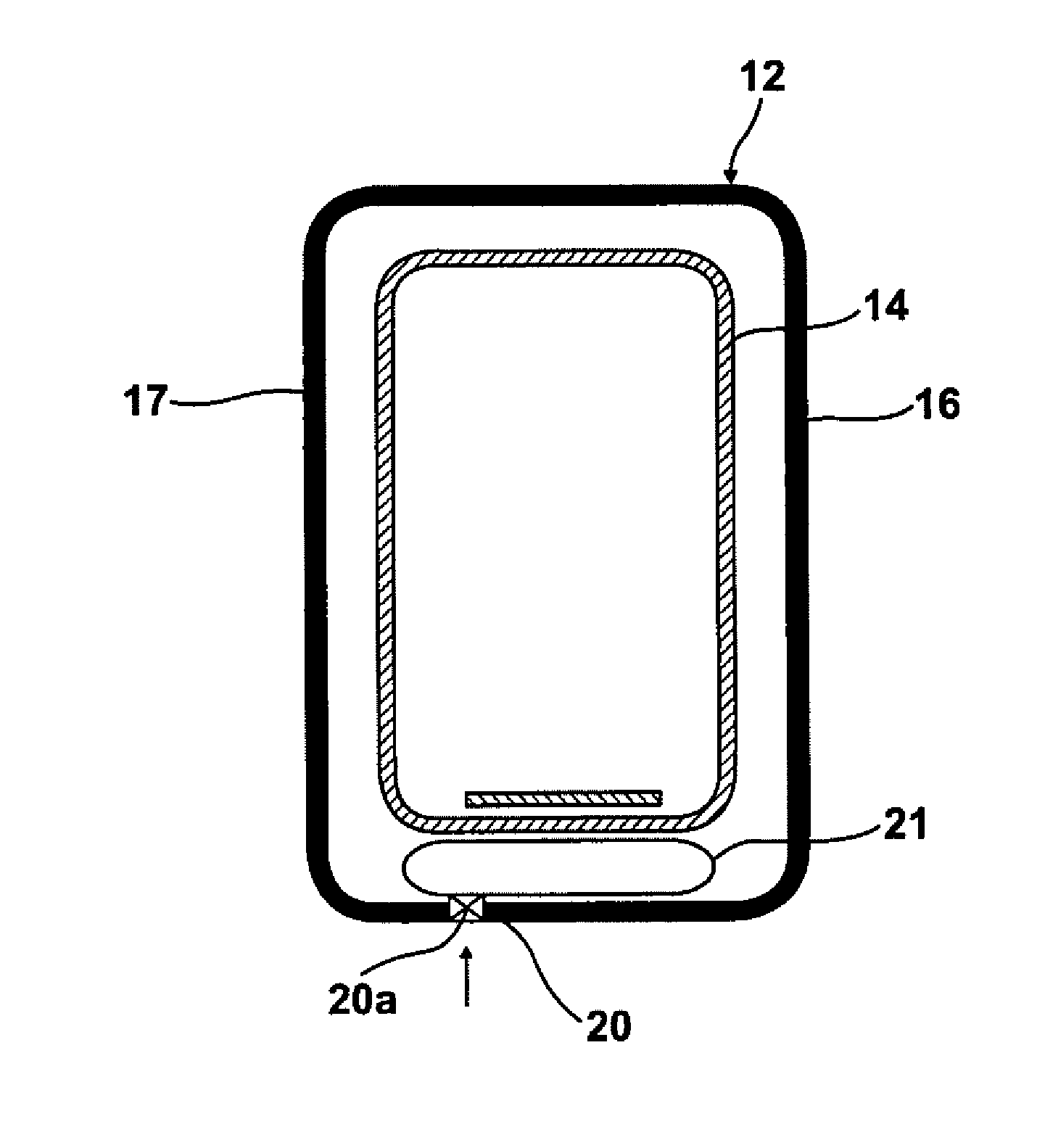
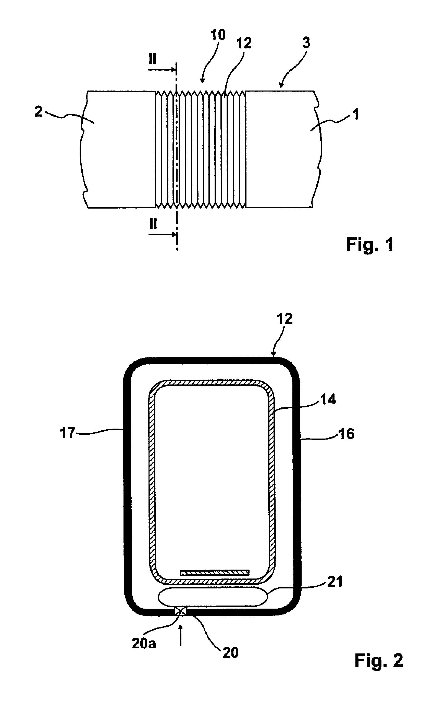
[0016]The two carriages 1 and 2 of the rail vehicle 3 are connected to one another by means of the passageway 10 with the dual-wave bellows 12. The dual-wave bellows 12 comprises the inner bellows 14 and the outer bellows 16, wherein the two bellows 14 and 16 are disposed at a distance to one another to form an interior space 17. The outer bellows 16 has one opening 20, wherein an inflatable container 21 can be connected to the opening 20. This inflatable container 21 is, in particular, also stretchable, in a manner similar to a balloon. It is also conceivable, however, that the container only be designed to be inflatable, with the background that the maximal volume of said container 21, or the bladder, corresponds exactly to the displaced volume when the outer bellows deforms towards the inner bellows. The opening 20 may be provided with a valve 20a. The extent of the pressure increase in the interior space 17 can be established by means of the valve 20a, for example.


PUM


Abstract

A passageway between two carriages of a rail vehicle, in particular a high-speed rail vehicle, wherein the passageway comprises an inner bellows and, disposed at a distance to said, an outer bellows to form an interior space, wherein the two bellows are each attached to the end face of the vehicle, wherein the two bellows are each designed in their circumference in a box shape, and that the interior space contains a means for at least a partial pressure compensation.

Description

CROSS-REFERENCE TO RELATED APPLICATIONS[0001]This application claims priority of European Patent Application EP 11 001 263.0 filed Feb. 16, 2011, and European Patent Application EP 11 001 681.3 filed Mar. 7, 2011.FIELD OF THE INVENTION[0002]The invention relates to a passageway between two carriages of a rail vehicle, in particular a high-speed rail vehicle, wherein the passageway comprises an inner bellows and, disposed at a distance to said, an outer bellows, forming an interior space, wherein the two bellows are each attached to the end face of the vehicle, wherein the two bellows are each box shaped in their circumference.BACKGROUND OF THE INVENTION[0003]Passageways, in particular for high-speed rail vehicles, are sufficiently known from the prior art. The passageways typically comprise two bellows, wherein the bellows encompass, in a box shape, a passageway bridge between the two carriages of a rail vehicle. A bellows construction of this type is “pressure-tight”; by “pressure-...

Claims


Application Information

Patent Timeline
Patent Type & Authority Applications(United States)
IPC IPC(8): B61D17/22
CPCB61D17/22
Inventor GOEBELS, ANDREJUNKE, VOLKER
Owner HUBNER GMBH
Why Eureka
Try Eureka