Locking device for a battery block of ground transportation vehicle

A technology of transportation tools and locking devices, which is applied in the field of locking devices of battery blocks, can solve problems such as roller contact surface sinking, and achieve the effect of easy removal

Active Publication Date: 2011-03-23
JUNGHEINRICH AG
View PDF5 Cites 23 Cited by
  • Summary
  • Abstract
  • Description
  • Claims
  • Application Information

AI Technical Summary

Problems solved by technology

Here, collisions during driving can cause sinking in the contact surface of the rollers, so that considerable force is required when removing the battery pack, since the breakaway force must first be overcome

Method used


Image

  • Locking device for a battery block of ground transportation vehicle
  • Locking device for a battery block of ground transportation vehicle
  • Locking device for a battery block of ground transportation vehicle

Examples


Embodiment Construction

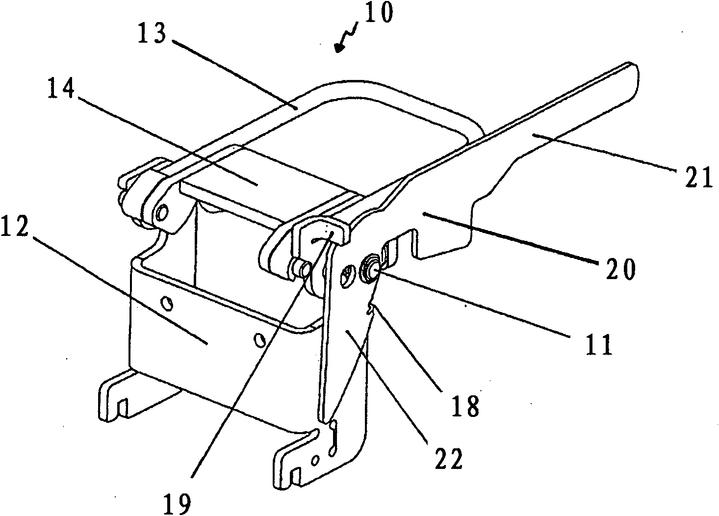
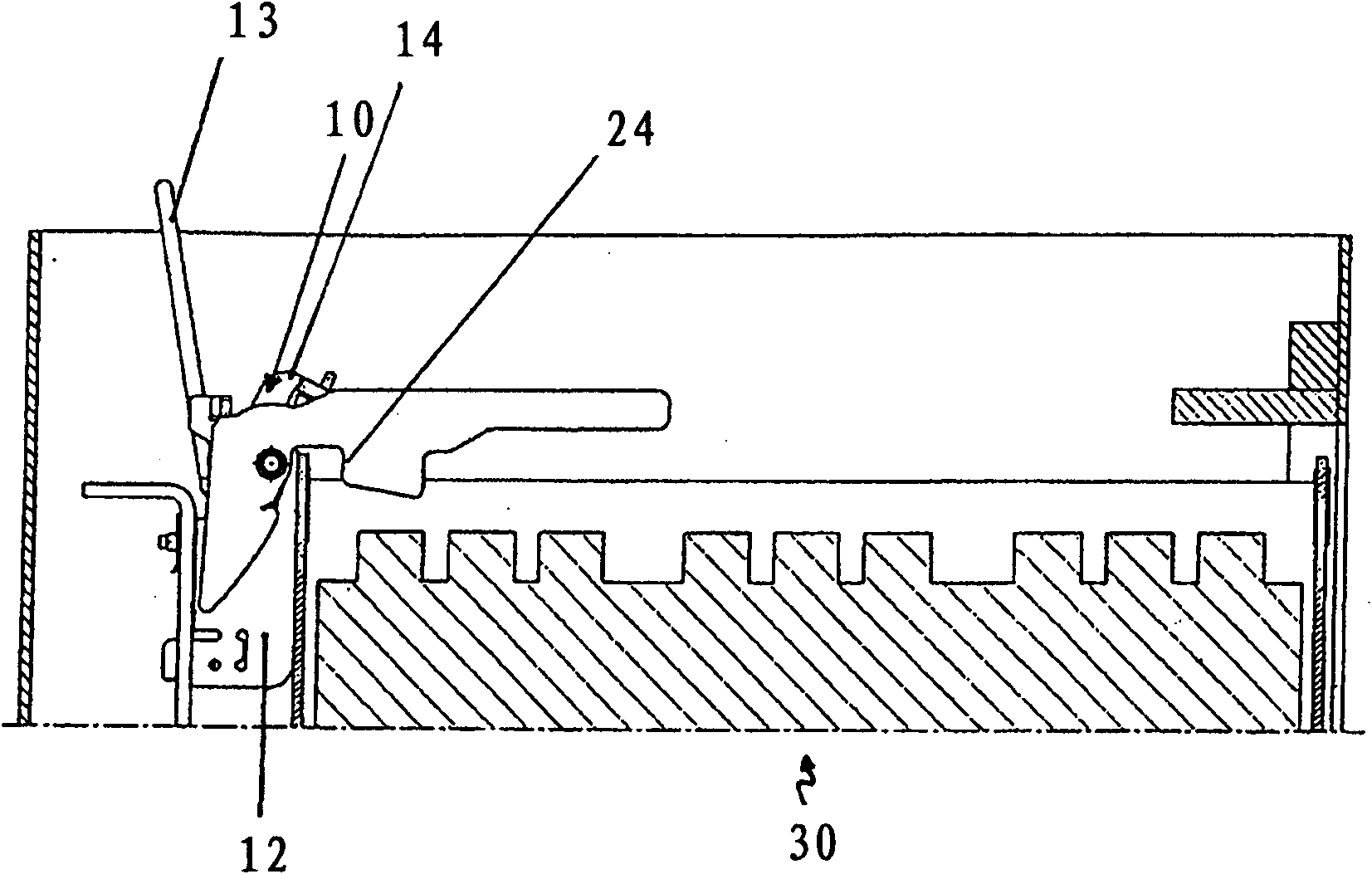
[0027] figure 1 A locking device is shown, which comprises a battery lock 10 and a removal lever 20 . The battery lock 10 has a support device 12 on which a first arcuate lever 13 is articulated. The second lever 14 is articulated to the first lever 13 by means of bearing bolts.

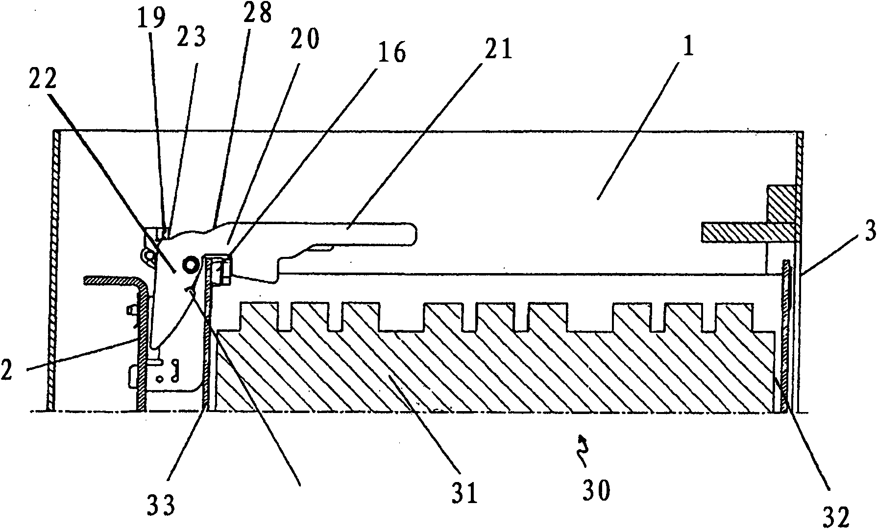
[0028] The removal lever 20 is mounted pivotably about the shaft 11 by means of screws connected to the support device 12 . The removal lever 20 has a first lever arm forming the handle section 21 and a second lever arm bent approximately at right angles relative to the first lever arm, which forms the lever section 22 . If the battery lock 10 is in the locked position, the handle section 21 is parallel to the first lever 13 of the battery lock 10 in the rest position of the removal lever. A stop 23 is formed on the end of the lever section 22 close to the shaft 11, and this stop 23 abuts against the corresponding stop 19 in the rest position of the extraction lever 20, which is formed by the bend...


PUM


Abstract

A locking device for a battery block of a ground transportation vehicle comprises the following components: a battery lock which is used for detachably locking a battery block in a frame of a ground transportation vehicle; and a removing lever which singly supports around an axle that is fixed on the ground transportation vehicle for assisting the battery block removing, wherein the removing lever is provided with a handle section composed of a first lever arm and a lever section composed of a second lever arm. The lever section partially pushes the battery block from the frame in removing.

Description

technical field [0001] The invention relates to a locking device for a battery pack of a ground vehicle according to claim 1 . Background technique [0002] Such a locking device is known, for example, from DE 10 2006 057 490 A1. The two levers of the locking device form a toggle lock, wherein the first lever is mounted around a shaft fastened to the ground vehicle. The second lever is pivotally supported on the first lever and grips the wall of the battery block by means of a buffer. In the unlocked position, the battery block can be moved out horizontally to one side. [0003] In known ground vehicles, the batteries are usually housed in a roller system. In this case, collisions during driving can cause sinking in the contact surface of the rollers, so that considerable force is required when removing the battery pack, since the breakaway force must first be overcome. Furthermore, the battery rests against the stop after unlocking, so that little or no space is left fo...

Claims


Application Information

Patent Timeline
Patent Type & Authority Applications(China)
IPC IPC(8): B60S5/06B66F9/06B60K1/04
CPCB60Y2200/15Y02T90/124B66F9/07536B60K1/04
Inventor H·洛曼
Owner JUNGHEINRICH AG
Why Eureka
Try Eureka