Workpiece vacuum sputtering method and device

A vacuum sputtering and workpiece technology, which is applied in vacuum evaporation plating, sputtering plating, ion implantation plating, etc., can solve the problems of time-consuming, affecting the sputtering process effect, low yield, etc., and achieve the best sputtering effect , save time and increase productivity

Inactive Publication Date: 2011-03-23
SHENZHEN XINJINGYUAN TECH
View PDF3 Cites 3 Cited by
  • Summary
  • Abstract
  • Description
  • Claims
  • Application Information

AI Technical Summary

Problems solved by technology

After the sputtering is completed, the cavity needs to be opened to take out the sputtered shell. At this time, the cavity loses its vacuum state, and the target in the cavity will be oxidized in contact with the air, which will affect the next sputtering process. Effect
And when the next process is carried out, the cavity needs to be evacuated from atmospheric pressure to vacuum again, and then the shell is preheated and sputtered in sequence. This process is time-consuming, resulting in low yield

Method used


Image

  • Workpiece vacuum sputtering method and device
  • Workpiece vacuum sputtering method and device
  • Workpiece vacuum sputtering method and device

Examples


Embodiment Construction

[0010] The workpiece vacuum sputtering method of the present invention will be further described in detail below in conjunction with the accompanying drawings and embodiments.

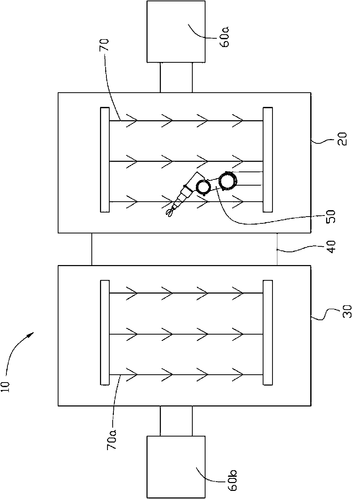
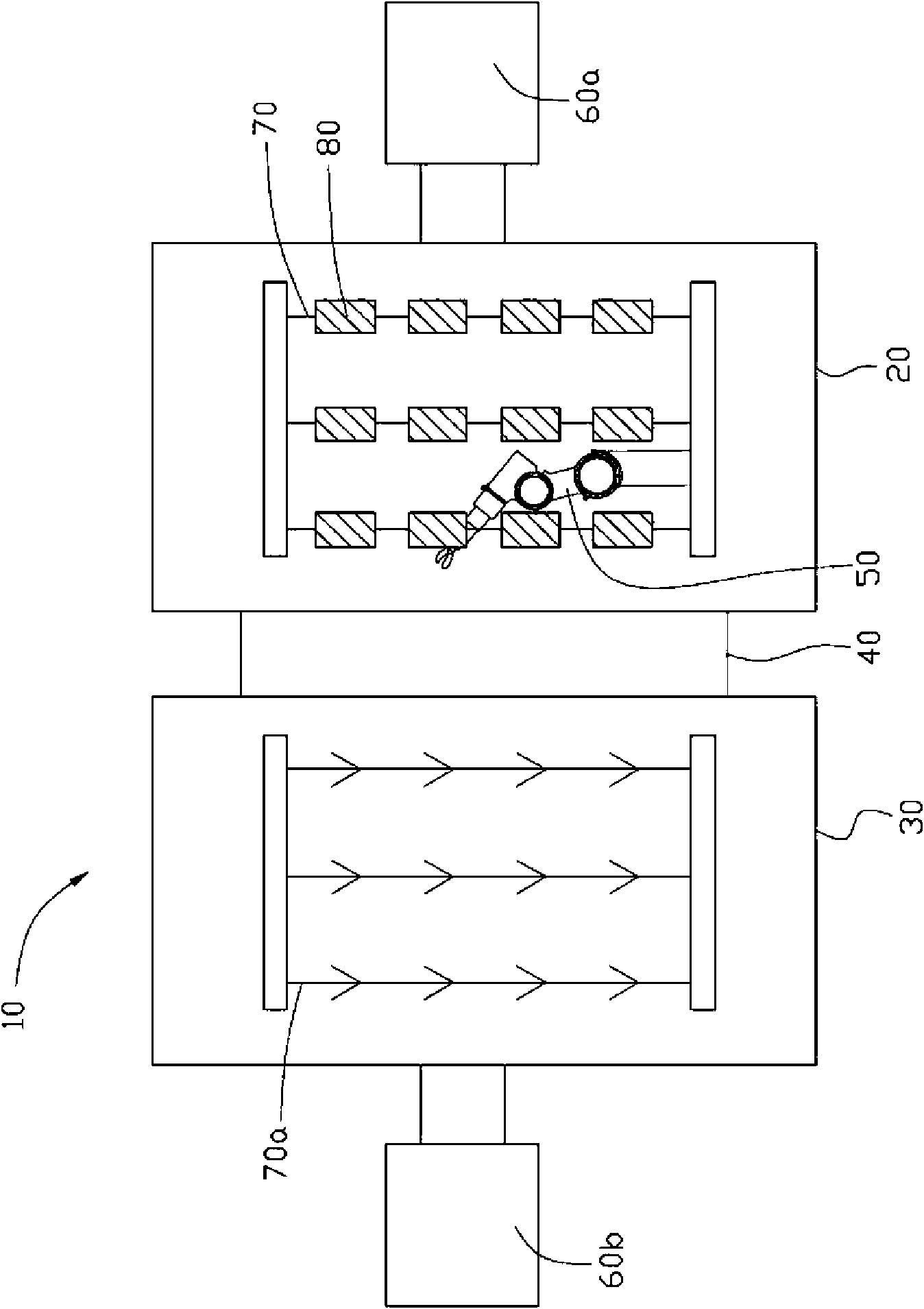
[0011] refer to figure 1 , the specific embodiment of the present invention provides a vacuum sputtering device 10 . The vacuum sputtering device 10 includes a first chamber 20, a second chamber 30, an isolation mechanism 40, an exchange mechanism 50, and vacuum machines 60a, 60b.

[0012] A first hanger 70 and a second hanger 70 a are respectively provided in the first chamber 20 and the second chamber 30 for hanging workpieces. The isolation mechanism 40 is disposed between the first chamber 20 and the second chamber 30 to selectively control whether the two chambers 20 , 30 are connected. The exchange mechanism 50 is arranged in the first chamber 20 or the second chamber 30 for exchanging the hangers 70 and 70a in the two chambers 20 and 30, figure 1 In the description, the exchanging mechanism 5...


PUM


Abstract

The invention relates to a workpiece vacuum sputtering method which is applied to a vacuum sputtering device provided with two communicated chambers. The vacuum sputtering device comprises a first chamber, a second chamber, a first lifting frame arranged in the first chamber, and a second lifting frame arranged on the second chamber. The method comprises the following steps: placing a first workpiece on the first lifting frame in the first chamber, and preheating the first workpiece; exchanging the first lifting frame in the first chamber with the second lifting frame in the second chamber; sputtering the preheated first workpiece in the second chamber; exchanging the second lifting frame in the first chamber with the first lifting frame in the second chamber; and taking out the sputteredfirst workpiece from the first chamber. The first chamber is used for preheating the workpiece, the second chamber is used for sputtering, and when the workpiece is subject to sputtering in the second chamber, the workpiece also can be taken, placed and preheated simultaneously in the first chamber, thus the yield is improved, and target materials in the second chamber is difficult to oxidize.

Description

technical field [0001] The invention relates to a sputtering method and device, in particular to a workpiece vacuum sputtering method and device. Background technique [0002] General consumer electronic products such as mobile phones or computers can use physical vapor deposition (Physical Vapor Deposition; PVD) process to decorate the casing of the coating. This process uses a single chamber for reaction. Then close the cavity and then vacuumize it. After the vacuum state is formed in the cavity, the shell is heated, and then the shell is sputtered. After the sputtering is completed, the cavity needs to be opened to take out the sputtered shell. At this time, the cavity loses its vacuum state, and the target in the cavity will be oxidized in contact with the air, which will affect the next sputtering process. Effect. And when the next process is carried out, the chamber needs to be evacuated from atmospheric pressure to vacuum again, and then the shell is preheated and s...

Claims


Application Information

Patent Timeline
Patent Type & Authority Applications(China)
IPC IPC(8): C23C14/34C23C14/54C23C14/56
CPCC23C14/564C23C14/34C23C14/50
Inventor 陈杰良魏朝沧张庆州简士哲凌维成王仲培吴佳颖黄建豪洪新钦廖名扬蔡泰生裴绍凯
Owner SHENZHEN XINJINGYUAN TECH
Why Eureka
Try Eureka