Magnetron sputtering target and magnetron sputtering device adopting same

A magnetron sputtering device and magnetron sputtering technology, applied in sputtering coating, ion implantation coating, coating and other directions, can solve the problems of reducing the utilization rate of target material, uneven particle distribution, affecting the quality of coating and so on , to achieve the effect of improving the utilization rate of the target material, improving the uniformity of the coating, and increasing the number of impacts

Inactive Publication Date: 2011-03-23
HONG FU JIN PRECISION IND (SHENZHEN) CO LTD +1
View PDF0 Cites 7 Cited by
  • Summary
  • Abstract
  • Description
  • Claims
  • Application Information

AI Technical Summary

Problems solved by technology

In the existing magnetron sputtering target, the magnetic core used is fixed relative to the coating material and the substrate to be coated. Due to the performance difference between the magnetic cores, part of the Ar + Particles cannot be absorbed by the magnetic field and some are too concentrated in the magnetic field range, resulting in Ar + Particles are unevenly distributed around the magnetron sputtering target, which affects the quality of the coating on the one hand and reduces the utilization of the target on the other hand

Method used


Image

  • Magnetron sputtering target and magnetron sputtering device adopting same
  • Magnetron sputtering target and magnetron sputtering device adopting same
  • Magnetron sputtering target and magnetron sputtering device adopting same

Examples


Embodiment Construction

[0012] The present invention will be further described in detail below in conjunction with the accompanying drawings.

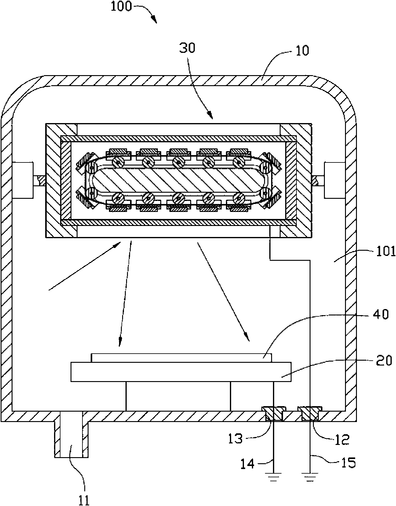
[0013] Such as figure 1 As shown, a magnetron sputtering device 100 provided in an embodiment of the present invention is used for coating a substrate 40 to be coated by impacting coating particles on a target. In this embodiment, the coating particles are Ar + particle. The magnetron sputtering device 100 includes a shield 10 , a substrate holder 20 and a magnetron sputtering target 30 . The shielding cover 10 is formed with a first cavity 101 , and the substrate carrier 20 and the magnetron sputtering target 30 are both located in the first cavity 101 . The substrate carrying seat 20 is disposed facing the magnetron sputtering target 30 , and is used for carrying the substrate 40 to be coated. The magnetron sputtering target 30 is pivotally connected to the inner wall of the shield 10 .

[0014] The shielding cover 10 is provided with a vacuum hole 11 ...


PUM


Abstract

The invention relates to a magnetron sputtering device which comprises a shielding cover, a substrate bearing seat and a magnetron sputtering target, wherein the shielding cover is provided with a first cavity, and the substrate bearing seat, a substrate and the magnetron sputtering target are positioned in the first cavity; the substrate bearing seat is arranged opposite to the magnetron sputtering target, the substrate is installed on the substrate bearing seat, and the magnetron sputtering target is pivoted on the inner wall of the shielding cover; the magnetron sputtering target comprises a target seat, at least one target material, a plurality of magnetic cores and a magnetic core translation mechanism, and the target material is fixed on the target seat; the plurality of magnetic cores are fixed on the magnetic core translation mechanism; the magnetic properties of every two adjacent magnetic cores are opposite; the magnetic core translation mechanism comprises a supporting plate, a plurality of roll shafts and transmission strips, and the edge of the supporting plate is fixed on the target seat and is parallel with the target material; the plurality of roll shafts are arranged on the supporting plate and can rotate relative to the supporting plate; the transmission strips are arranged around the plurality of roll shafts and the supporting plate; and the magnetic core translation mechanism can drive the plurality of magnetic cores to translate relative to the target material. The invention also provides a magnetron sputtering target.

Description

technical field [0001] The invention relates to a magnetron sputtering device, in particular to a magnetron sputtering target for vacuum coating and a magnetron sputtering device using the magnetron sputtering target. Background technique [0002] The existing vacuum coating is generally by emitting Ar + Particles hit the coating material in the vacuum chamber, so that the atoms of the material are separated from the heating source and hit the surface of the object to be coated to form a film layer. [0003] Magnetron sputtering target is one of the important equipment for vacuum coating. In the existing magnetron sputtering target, the magnetic core used is fixed relative to the coating material and the substrate to be coated. Due to the performance difference between the magnetic cores, part of the Ar + Particles cannot be absorbed by the magnetic field and some are too concentrated in the magnetic field range, resulting in Ar + The particles are unevenly distributed ar...

Claims


Application Information

Patent Timeline
Patent Type & Authority Applications(China)
IPC IPC(8): C23C14/35
CPCH01J37/3408H01J37/3455C23C14/35H01J37/3452
Inventor 裴绍凯
Owner HONG FU JIN PRECISION IND (SHENZHEN) CO LTD
Why Eureka
Try Eureka