
Temperature sensor

A temperature sensor and electronic device technology, applied to thermometers, thermometer parts, instruments, etc., can solve the problems of high cost, deviation, and difficulty in accurately measuring junction temperature of temperature detection circuits, and achieve electrical insulation and accurate operation control , the effect of accurate measurement

Inactive Publication Date: 2011-03-23
MITSUBISHI MATERIALS CORP
View PDF1 Cites 12 Cited by
  • Summary
  • Abstract
  • Description
  • Claims
  • Application Information

AI Technical Summary

Problems solved by technology

[0006] That is, the prior art described above has the problem of estimating the temperature of the electronic device by assembling a temperature sensor on a substrate mounted with an electronic device or a heat radiation plate on which the electronic device is mounted, and measuring the temperatures of the substrate and the heat radiation plate with the temperature sensor. However, it is still difficult to accurately measure the junction temperature due to deviations caused by the influence of the thermal resistance of the substrate or heat sink
In addition, when the temperature sensor is mounted on the same substrate on which the electronic components are mounted, there is a problem of high cost of the temperature detection circuit in order to electrically insulate the large current circuit or the inverter circuit formed on the substrate.

Method used


Image

  • Temperature sensor
  • Temperature sensor
  • Temperature sensor

Examples


Embodiment Construction

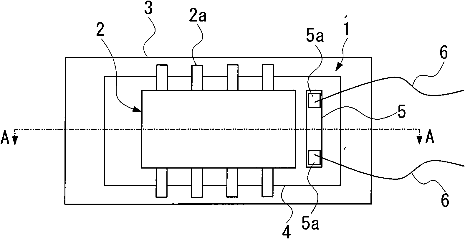
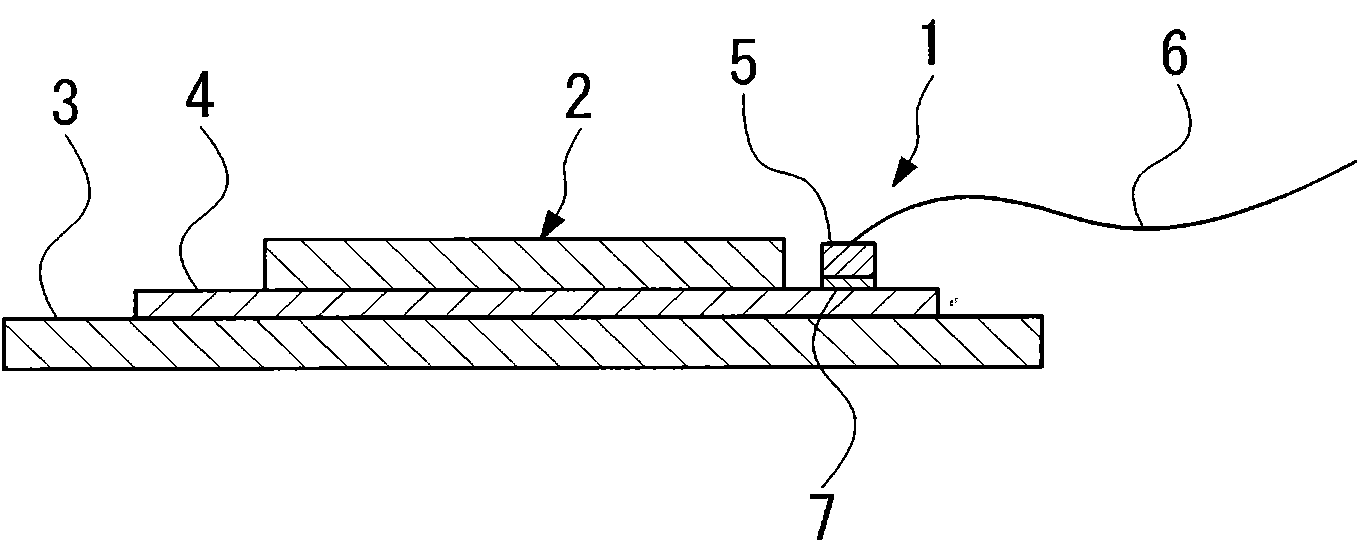
[0023] Below, refer to figure 1 and figure 2 A first embodiment of the temperature sensor of the present invention will be described. In addition, in each drawing used for the following description, in order to make each member recognizable or easily recognizable, the scale is changed suitably.

[0024] like figure 1 and figure 2 As shown, the temperature sensor 1 of this embodiment is used, for example, to measure the temperature of an electronic device 2 that generates heat during operation. between the substrates 3 , and conduct the heat of the electronic device 2 to the substrate 3 ;

[0025] The above-mentioned electronic device 2 is, for example, a transistor such as a power transistor or a power FET. That is, when the electronic device 2 is a transistor, the temperature sensor 1 of this embodiment measures the junction temperature for driving control of the transistor.

[0026] The above-mentioned substrate 3 is, for example, a printed substrate formed with patt...


PUM


Abstract

The present invention provides a temperature sensor which can restrain the effect of the thermoresistance of a substrate or a heat discharging plate and can be electrically insulated from a circuit on the substrate. The temperature sensor is provided with the following components: a heat conduction sheet (4) which is sandwiched between the electronic device (2) and a substrate (3) that is equipped with the electronic device (2) through a clinging state, and causes the heat of the electronic device (2) to the substrate (3); and a thermal sensitive component (5) which is equipped on the heat conduction sheet (4). Therefore, the heat conduction sheet (4) which closely clings on to the electronic device (2) efficiently transfers heat to the thermal sensitive component (5) without passing through the substrate (3). The effect of the thermoresistance of substrate (3) can be restrained for accurately measuring the temperature of the electronic device (2).

Description

technical field [0001] The invention relates to a temperature sensor capable of accurately measuring the temperature of electronic devices such as transistors. Background technique [0002] In the past, when measuring the temperature of electronic devices that generate heat, such as transistors, for example, by mounting a temperature sensor such as a chip thermistor on a substrate assembled with electronic devices or a heat sink mounted on the electronic device, heat is released through the substrate or board to measure the temperature of electronic components. That is, in a power transistor or a power FET, etc., in order to protect it from damage due to temperature rise, the junction temperature is measured by an installed temperature sensor, and when it becomes above a predetermined temperature, control is performed according to the temperature, such as limiting or stopping operation. Therefore, a temperature sensor is installed near these electronic devices on a mounting...

Claims


Application Information

Patent Timeline
Patent Type & Authority Applications(China)
IPC IPC(8): G01K1/16
Inventor 山下信之北口诚
Owner MITSUBISHI MATERIALS CORP
Learn More