
Crystallizer

A crystallizer and water outlet technology, which is applied in the field of crystallization devices, can solve the problems of increasing the internal defects of the billet, uneven ingot structure, and upper crystallization center, etc., so as to reduce dummy resistance, uniform ingot structure, and wear degree Improved effect

Inactive Publication Date: 2011-03-30
CNMC ALBETTER ALBRONZE
View PDF5 Cites 5 Cited by
  • Summary
  • Abstract
  • Description
  • Claims
  • Application Information

AI Technical Summary

Problems solved by technology

In addition, due to the action of the ingot's own gravity, the lower part of the solidified shell is more tightly attached to the mold than the upper part, so the lower part of the contact length between the solidified shell and the crystallizer is greater than the upper part, resulting in the lower part of the dummy resistance being greater than the upper part.
[0004] In addition, the temperature of the melt in the upper part of the mold is higher than that in the lower part during horizontal continuous casting, so the crystallization of the ingot in the upper part of the mold is later than that in the lower part. Through the observation and measurement of the low-magnification sample of the ingot, it is found that there is The phenomenon that the crystallization center is on the upper side, which causes the inhomogeneity of the ingot structure
When the pouring speed is increased, the eccentric value of the crystallization center will become smaller, but if the ingot casting speed is too fast, the internal defects of the billet will be increased, and even the copper strip will be leaked
Currently, there is no good solution

Method used


Image

  • Crystallizer
  • Crystallizer

Examples


Embodiment Construction

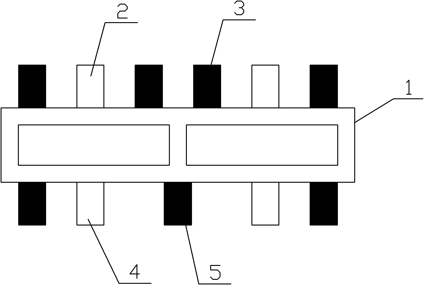
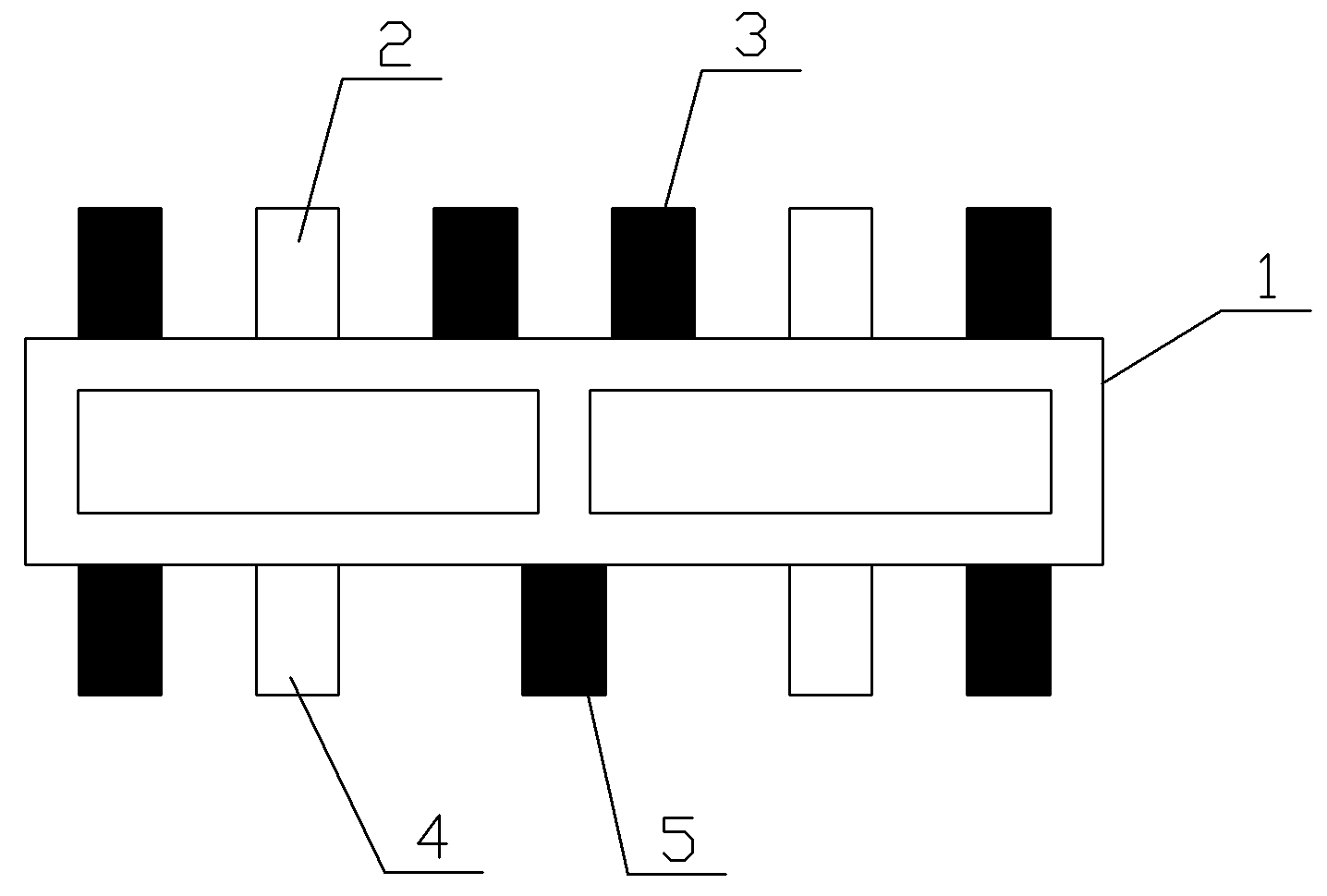
[0011] Refer to the attached figure 1 A crystallizer of the present invention is described in detail below.

[0012] A crystallizer of the present invention, its structure includes a crystallizer shell 1, the upper part of the crystallizer shell 1 is provided with an upper water outlet 3 and an upper water inlet 2, and the lower part of the crystallizer shell 1 is provided with a lower outlet The water inlet 5 and the lower water inlet 4, the upper water inlet 2 and the lower water inlet 4 are respectively two, the upper water inlet 2 and the lower water inlet 4 are arranged symmetrically, and the number of the upper water outlets 3 is large According to the number of the lower water outlets 5, the lower water outlets 5 and the lower water inlets 4 are arranged in a staggered arrangement.

[0013] There are four upper water outlets 3 and three lower water outlets 5 .

[0014] Since the design adopts four upper water outlets 3 and three lower water outlets 5, the cooling stre...


PUM


Abstract

The invention discloses a crystallizer, belonging to crystallizing devices, which structurally comprises a shell body of the crystallizer, wherein upper water outlets and upper water inlets are arranged on the upper part of the shell body of the crystallizer; lower water outlets and lower water inlets are arranged on the lower part of the shell body of the crystallizer; the upper water inlets and the lower water inlets are respectively two in quantity; the upper water inlets and the lower water inlets are symmetrically arranged; the amount of the upper water outlets is larger than the amount of the lower water outlets; and the lower water outlets and the lower water inlets are arranged in a staggered mode. Compared with the prior art, the crystallizer of the invention has the advantages that the temperature on the surface of cast ingots is reduced so that the tissues of the upper surfaces and the lower surfaces of the cast ingots are uniform; the cooling strength of a graphite plate on the crystallizer is enhanced, and the cooling strength on the lower surface of the crystallizer is reduced so that the upper and the lower cast ingots in the crystallizer can be simultaneously crystallized; the abrasion degree of the graphite plate on the lower surface of the crystallizer is improved to a certain extent; and the service life of the graphite plate is increased, and the like, therefore, the crystallizer has good popularization and application values.

Description

technical field [0001] The invention relates to a crystallization device, in particular to a crystallizer which can reduce dummy ingot resistance on the lower surface of the crystallizer, improve the quality of the center line of the ingot and the slab, and prolong the service life of the crystallizer. Background technique [0002] Usually, the crystallizers used in horizontal continuous casting to produce bronze have the same amount of water entering and exiting the upper and lower surfaces, and adopt two-inlet and three-outlet or two-inlet and four-outlet molds, and the number of inlets and outlets on the upper and lower surfaces is symmetrical. However, the traditional crystallizer design does not take into account the difference in the cooling degree of the upper and lower surfaces of the ingot. After dismantling the discarded crystallizer, it can be found that the wear degree of the graphite plates on the upper and lower surfaces of each crystallizer is different, and th...

Claims


Application Information

Patent Timeline
IPC IPC(8): B22D11/045B22D11/055
Inventor 郭丽丽张西军李学帅梁琦明田英明郑朋艳张伟
Owner CNMC ALBETTER ALBRONZE
Learn More