Supercharge Your Innovation With Domain-Expert AI Agents!

Gas supply device and vacuum processing apparatus

一种气体供给、气体流动的技术,应用在真空处理设备领域,能够解决接触和破坏等问题,达到减少数量、改进气体响应、减少成本的效果

Active Publication Date: 2012-11-28
CANON ANELVA CORP
View PDF1 Cites 0 Cited by
  • Summary
  • Abstract
  • Description
  • Claims
  • Application Information

AI Technical Summary

Problems solved by technology

In addition, the flexible tube may contact and damage other components of the vacuum vessel during the door opening / closing operation

Method used


Image

  • Gas supply device and vacuum processing apparatus
  • Gas supply device and vacuum processing apparatus
  • Gas supply device and vacuum processing apparatus

Examples


Embodiment Construction

[0023] Preferred embodiments of the present invention will now be described with reference to the accompanying drawings. It should be noted that members, arrangements, etc. set forth in the embodiments are merely examples of the present invention and do not limit the scope of the present invention, but various modifications can be made without departing from the present invention.

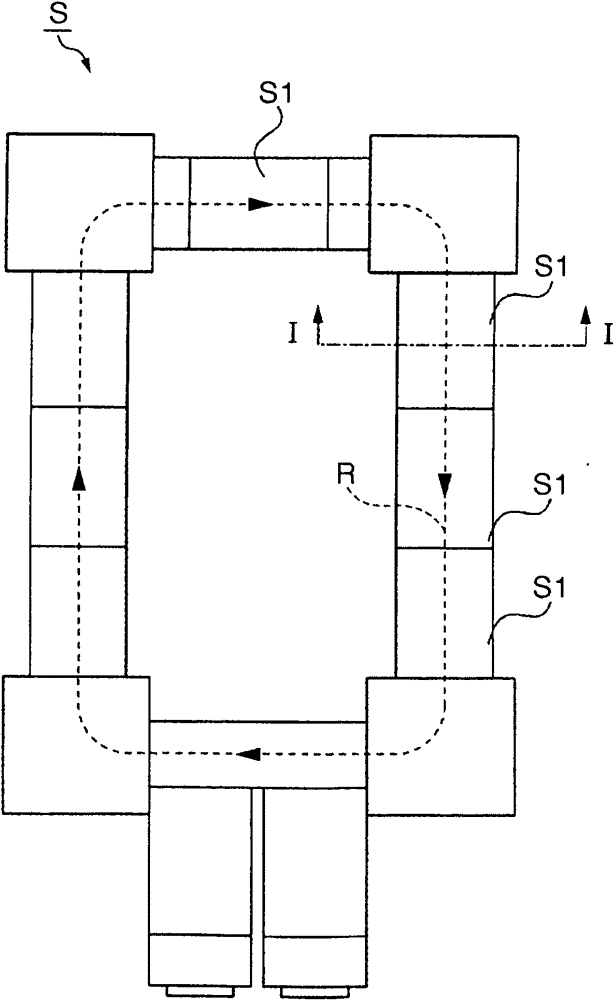
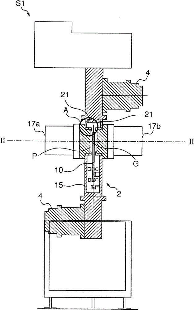
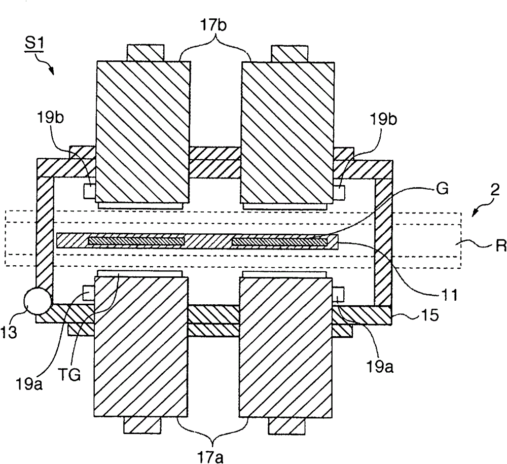
[0024] Figures 1 to 7 Examples of the present invention are shown. figure 1 is a view of a schematic arrangement of an in-line deposition apparatus. figure 2 is a schematic cross-sectional view of the deposition chamber taken along line I-I. image 3 is a schematic cross-sectional view of the deposition chamber taken along line II-II. Figure 4 is a view of the gas system. Figure 5 yes figure 2 An enlarged cross-sectional view of part A in . Figure 6 It is an enlarged view of the connection part of the gas pipeline. Figure 7 is a side view of the seal member.

[0025] figure 1 The in...


PUM


Abstract

A gas supply device includes a chamber frame, a door which is attached to the chamber frame to be able to open and close the door, and has a cathode, a door-side introduction block which is attached to the door and has a gas flow path for supplying discharge gas to the cathode, and a chamber-side introduction block which is attached to the chamber frame and has a gas flow path for supplying discharge gas introduced outside from the chamber frame to the door-side introduction block. When the door is closed, the gas flow path of the door-side introduction block and the gas flow path of the chamber-side introduction block communicate with each other.

Description

technical field [0001] The present invention relates to a gas supply device capable of connecting gas pipes according to opening / closing of a gas supply door of the vacuum device and vacuum processing equipment having the gas supply device. Background technique [0002] For example, in the sputtering apparatus disclosed in Japanese Patent Laid-Open No. 2002-68476, the cathode is attached to a door that opens and closes via a hinge relative to the vacuum container. The gas pipe is arranged using a flexible pipe, and the discharge gas is supplied to the cathode from outside the door via the gas pipe. [0003] When multiple cathodes are attached to one door, the difference in length between the pipes for supplying gas to the respective cathodes results in a difference in the timing of supplying the gas to the respective cathodes. To prevent this, the pipes need to be arranged to have the same pipe route length. [0004] However, arranging the flexible tubing outside the vacuu...

Claims


Application Information

Patent Timeline
Patent Type & Authority Patents(China)
IPC IPC(8): C23C14/34C23C14/56
CPCC23C16/507C23C16/45517Y10T137/8593
Inventor 植野伸彦宫内信人若林秀纪
Owner CANON ANELVA CORP
Features
  • R&D
  • Intellectual Property
  • Life Sciences
  • Materials
  • Tech Scout
  • Unparalleled Data Quality
  • Higher Quality Content
  • 60% Fewer Hallucinations
Learn More