Refluxing system for linear sliding rail

A linear slide rail and slide rail technology, applied in the direction of linear motion bearings, bearings, shafts and bearings, etc., can solve the problem that the first circulation path and the second circulation path have many structures, which are prone to noise and high processing costs. problems, to achieve convenient and rapid mass production, reduce processing costs, and avoid contact noise

Active Publication Date: 2011-03-30
HIWIN TECH
View PDF3 Cites 3 Cited by
  • Summary
  • Abstract
  • Description
  • Claims
  • Application Information

AI Technical Summary

Problems solved by technology

[0004] U.S. Patent No. US5911509, such as Figure 15 As shown, the curved surface return path of the circulation path and the return path are formed using the embedded injection method, which is directly integrally molded on the slider 61 in the injection molding mold with an injection molding machine on the outer side of the bottom of the slider 61. The curved surface return path and the return path 62 are formed by combining the end caps with the curved surface return path at both ends of the slider 61. The design of this structure has the following disadvantages: because each metal slider 61 needs to be embedded in the mold for Injection molding processing, so the processing accuracy of the slider 61 must be improved to match the mold, otherwise it is easy to cause plastic or rubber overflow due to inaccurate mold covering, or collision between the mold and the slider 61, which will cause mold damage. damage, and the processing accuracy of the slider 61 is also related to the processing cost of the slider 61, the higher the precision of the slider 61, the higher the processing cost
[0005] U.S. Patent No. US5102235, such as Figure 16 As shown, the shape of the return path is to extend a return portion 711 on the two end caps 71 to connect the two end caps 71. There is a half return path 712, and another half return path 721 is directly processed on the outer side of the bottom of the slider 72. With the cooperation of the two half return paths 712, 721, a complete return path is formed, and then matched with the end cover 71 The load path between the curved surface return path and the slide rail 73 and the end cover 71 forms a complete circulation path. The design of this structure has the following disadvantages: because half of the return path 721 is at the bottom of the metal slide block 72 The outer side is directly processed, so that half of the return path is made of metal products, and when the rolling elements moving in the circulation path are rolling without load, noise is likely to be generated between the metal half return path 721, and half of the return path is reflowed The path 721 is directly processed on the metal slider 72, so the semi-return path 721 of the metal slider 72 needs to be machined to a certain precision so that the rolling elements can roll smoothly, so it also has the defect of high processing cost
[0006] U.S. Patent No. US4869600, such as Figure 17 As shown, the slide block 81 is stacked with a first return piece 82 and a second return piece 83 in sequence on the two sides below, and cooperates with the end caps 84 at both ends of the slide block 81. Half of the first return path 811 is directly processed on the outside, and the other half of the first return path 821 is formed above the first return member 82, and half of the second return path 822 is formed below, and another half is formed above the second return member 83 The other half of the second return path 831 is combined into two complete first and second return paths by stacking to provide the return rolling of the two sets of rolling elements. The design of this structure has the following disadvantages: because half of the return path The first return path 811 is directly processed outside the bottom of the metal slide block 81, and the noise is likely to be generated between the metal rolling element and the metal semi-first return path 811, and the first circulation path and a The structure of the second circulation path is many and the design is complex. In addition to the addition of two first return parts 82 and two second return parts 83, the first return part 82 and the second return part 83 must also be connected with at least four locks. Fixed screw 85 for fixing
[0007] It can be seen that the current common linear slide rail return system, its no-load return path is mostly a combination of metal and plastic, this design will generate a lot of noise, and the embedded injection method can solve the noise problem, but the product accuracy The design must be high, which has the disadvantage of high cost

Method used


Image

  • Refluxing system for linear sliding rail
  • Refluxing system for linear sliding rail
  • Refluxing system for linear sliding rail

Examples


Embodiment 2

[0036] Example two such as Image 6 , Figure 7 , Figure 8 shown, including:

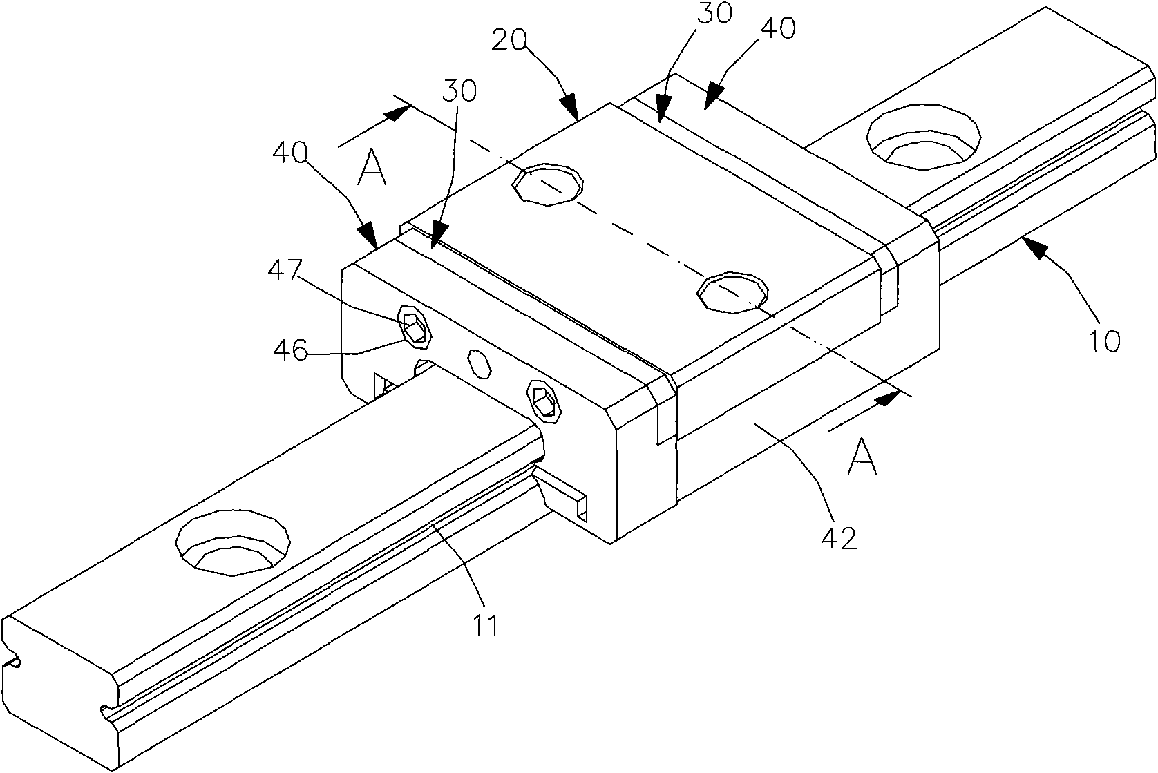
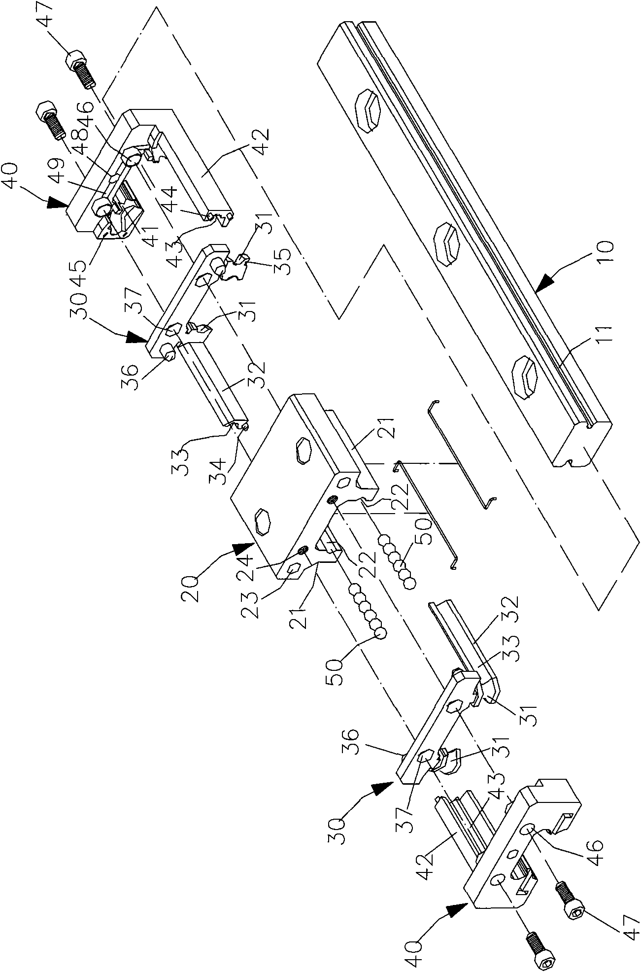
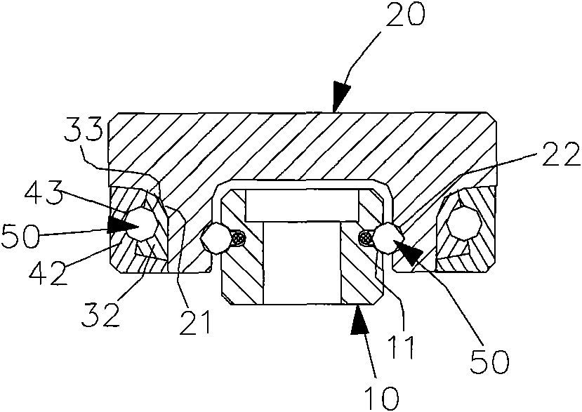
[0037] A slide rail 10A is made of metal, and two sides of the slide rail 10A are respectively provided with a slide rail groove 11A.

[0038] A slider 20A is made of metal, and a matching groove below is arranged to cooperate with the slide rail 10A for linear movement. The two outer sides below the slider 20A are respectively provided with a set of setting parts 21A, and the slider 20A is sheathed on the slider On the rail 10A, two sides adjacent to the slide rail 10 are respectively provided with a slider groove 22A, and the slider groove 22A and the two slide rail grooves 11A of the slide rail 10A respectively form a complete load path, and the slider groove 22A forms a complete load path respectively. The two ends of the block 20A are respectively provided with a limiting hole 23A and a locking hole 24A.

[0039] The two cover plates 30A are made of soft plastic material and are respective...

Embodiment 3

[0043] Embodiment three such as Figure 9 , Figure 10 , Figure 11 shown, including:

[0044] A slide rail 10B is made of metal, and two sides of the slide rail 10B are respectively provided with a slide rail groove 11B.

[0045] A slider 20B is made of metal, and a matching groove below is arranged to cooperate with the slide rail 10B for linear movement. The two outer sides below the slider 20B are respectively provided with a set of setting parts 21B, and the slider 20B is sleeved on the slider On the rail 10B, two sides adjacent to the slide rail 10 are respectively provided with a slide block groove 22B and the two slide rail grooves 11B of the slide rail 10B respectively form a complete load path, and the two ends of the slide block 20B are respectively provided with There are limiting holes 23B and locking holes 24B.

[0046] The two cover plates 30B are made of soft plastic material and are respectively arranged on the two ends of the slider 20B in an opposite man...

Embodiment 4

[0051] Example 4 as Figure 12 , Figure 13 , Figure 14 shown, including:

[0052] A slide rail 10C is made of metal, and two slide rail grooves 11C are respectively provided on two sides of the slide rail 10C.

[0053] A slider 20C is made of metal, and a matching groove at the bottom cooperates with the slide rail 10C to produce linear movement. The two outer sides below the slider 20C are respectively provided with a set of setting parts 21C, and the slider 20C is sleeved on the slider rail 10C, adjacent to the two sides of the slide rail 10C are respectively provided with two slide block grooves 22C and each slide rail groove 11C of the slide rail 10C to form a complete load path respectively, and the two ends of the slide block 20C are respectively provided with There are limiting holes 23C and locking holes 24C.

[0054] The two cover plates 30C are made of soft plastic material and are respectively arranged on the two ends of the slider 20C in a relative manner. T...


PUM


Abstract

The invention discloses a refluxing system for a linear sliding rail. In the system, a sliding block is arranged on the sliding rail; a cover plate and an end cover are arranged at the two ends of the sliding block respectively; inner refluxing blocks and outer refluxing blocks are respectively extended between the end plates and the end covers at the ends; a semi-refluxing path is respectively reserved between the inner refluxing blocks and the outer refluxing blocks so as to form a complete refluxing path; the two ends of the refluxing path and a load path are respectively connected to the two ends of the refluxing paths of two curved surfaces so as to form a complete circulating path; the end plates, the end covers, the extended inner refluxing block and the extended outer refluxing block are injected by common plastics; the formed refluxing path is made of a plastic material; therefore, the refluxing system has the advantages that: the system is convenient to manufacture, the cost is low and the use is quieter.

Description

technical field [0001] The invention relates to a return system of a linear slide rail. Background technique [0002] The linear slide rail for the slider to move, in order to reduce the friction coefficient of the slider movement and reduce the noise generated when the slider moves, usually a return system is set between the slider and the slide rail to provide ball circulation rolling, the return system includes two The return end cover is arranged at both ends of the slider, a plurality of load paths are located between the slider and the slide rail, and a plurality of no-load return paths pass through the slider, and a curved return path is also provided on the return end cover. The curved surface return path connects each load return path and each no-load path to form a complete circulation path, and the slider and slide rail are all metal designs because of the necessary load. [0003] At present, there are three main designs for the design of the curved surface retur...

Claims


Application Information

Patent Timeline
Patent Type & Authority Applications(China)
IPC IPC(8): F16C29/06
Inventor 陈琮仁游哲轩刘新平
Owner HIWIN TECH
Why Eureka
Try Eureka