
Combustor fire cover for gas stove and combustor of gas stove thereby

A technology for burners and gas stoves, applied in the directions of gas fuel burners, burners, combustion methods, etc., can solve the problems of influence, the user spends a long time to cook, and the area where the fire holes are distributed is limited, etc.

Inactive Publication Date: 2011-03-30
BSH ELECTRICAL APPLIANCES JIANGSU
View PDF9 Cites 24 Cited by
  • Summary
  • Abstract
  • Description
  • Claims
  • Application Information

AI Technical Summary

Problems solved by technology

[0002] In the existing gas stove burners, generally, the top surface of the burner is provided with an outer ring fire outlet and an inner ring fire outlet. In order to improve the heating efficiency of the burner and improve the heating effect, the outer ring cover of some burners A circle of fire holes is added near the edge of the inner ring fire cover, but still because of the limited distribution of fire holes on the burner, there is a large area between the fire rings without fire hole distribution, resulting in During the working of the burner, there is no flame in the place where there is no fire hole distribution, forming a heated low-temperature zone, and the bottom surface of the heated vessel is heated unevenly. Once the user puts the cooker on for heating or cooking, the corresponding The temperature will be lower where the area is larger and where the flame cannot directly touch, and the surface temperature of the bottom of the pot that is directly heated by the outer ring fire hole and the inner ring fire hole will be very high. In this way, not only does it take a long time for the user to cook , and relatively more gas will be consumed, resulting in low thermal efficiency and some adverse effects on the taste of food

Method used


Image

  • Combustor fire cover for gas stove and combustor of gas stove thereby
  • Combustor fire cover for gas stove and combustor of gas stove thereby
  • Combustor fire cover for gas stove and combustor of gas stove thereby

Examples


Embodiment Construction

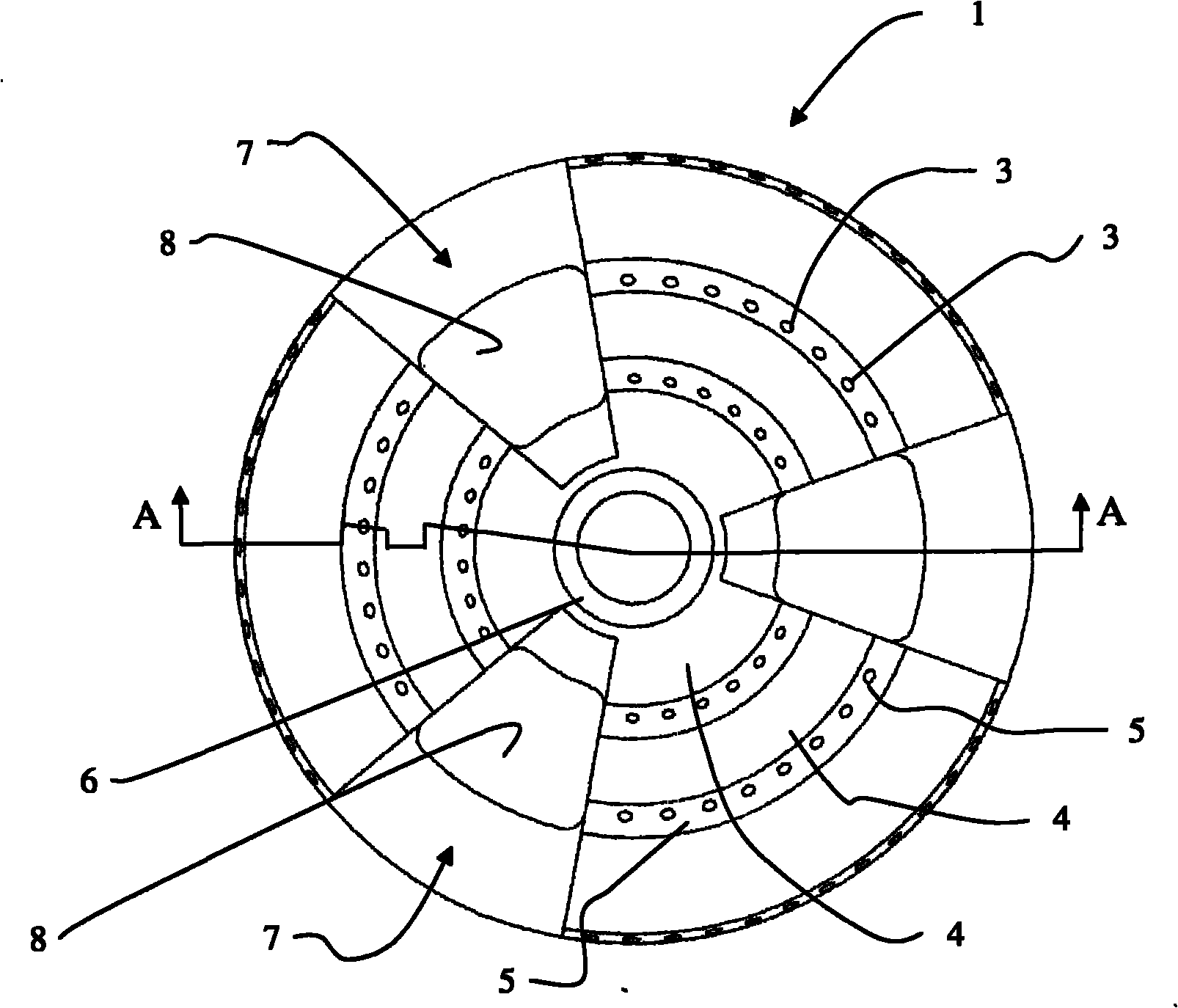
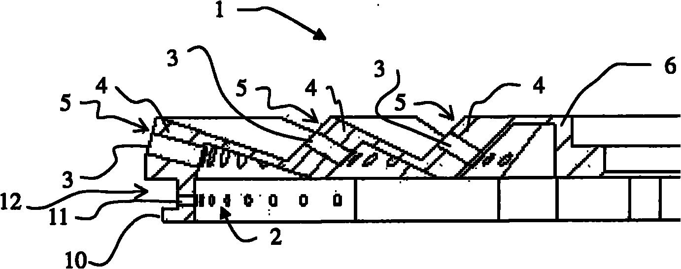
[0031] See attached Figure 1 to Figure 4 , the present invention provides a burner fire cover 1 for a gas stove, comprising a cover body 1 with a substantially circular shape and a base surface 9 of the cover body. The lower side of the cover body is recessed to form the cover body air chamber 2 . The cover is provided with a fire hole 3 penetrating the cover. At least one peak undulation 4 concentric with the cover is formed on the base surface of the cover. The peak undulation 4 comprises at least two discontinuously distributed peak undulation segments. Each of the peak-shaped undulating sections is formed with an outer slope 5 facing away from the center of the cover body. A fire hole 3 is arranged on the outer slope surface 5 . By setting at least one peak-shaped undulation 4 formed by at least two peak-shaped undulating sections concentric with the cover on the cover base surface of the burner fire cover, at the same time, the peak-shaped undulating segment is away ...


PUM


Abstract

The invention relates to a combustor fire cover for a gas stove and a combustor of the gas stove thereby. The combustor fire cover for the gas stove (1) comprises a cover body (1) with a cover body base plane (9), the cover body roughly presents a circle, a cover body gas containing cavity (2) is formed by the indent of the downside of the cover body, and the cover body is provided with fire outlets (3) penetrating through the cover body. The combustor fire cover is characterized in that at least a peak-shaped fluctuation (4) which is homocentric with the cover body is formed on the cover body base plane and comprises at least two peak-shaped fluctuation sections in disjunctive distribution, and an outer slope face (5) orientating the direction deviating from the centre of the cover body is formed on each peak-shaped fluctuation section and provided with the fire outlet (3). The fire cover realizes that the fire outlets on the combustor fire cover are distributed more uniformly, to ensure that the flames are distributed more uniformly when the combustor is at work, and the heating efficiency is improved.

Description

technical field [0001] The invention relates to a gas stove component, in particular to a burner fire cover for a gas stove and a gas stove burner using the burner fire cover. Background technique [0002] In the existing gas stove burners, generally, the top surface of the burner is provided with an outer ring fire hole and an inner ring fire hole. In order to improve the heating efficiency of the burner and improve the heating effect, the outer ring cover of some burners A circle of fire holes is added near the edge of the inner ring fire cover, but still because of the limited distribution of fire holes on the burner, there is a large area between the fire rings without fire hole distribution, resulting in During the operation of the burner, there is no flame in the place where there is no fire hole distribution, forming a heated low-temperature zone, and the bottom surface of the heated vessel is heated unevenly. The temperature will be lower where the area is larger an...

Claims


Application Information

Patent Timeline
Patent Type & Authority Applications(China)
IPC IPC(8): F23D14/46F23D14/48F23D14/58F23D14/02
CPCF23D14/06F23D2900/14062F23D14/58
Inventor 苗伟伟张神洲张新骆海涛
Owner BSH ELECTRICAL APPLIANCES JIANGSU
Learn More