Channel continuous noise detection method and device

A channel and noise technology, applied in the field of channel continuous noise detection, can solve the problems of interfering packet transmission, channel noise interference, unable to send data at the same time, etc.

Inactive Publication Date: 2011-03-30
LINK TECH INC
View PDF4 Cites 2 Cited by
  • Summary
  • Abstract
  • Description
  • Claims
  • Application Information

AI Technical Summary

Problems solved by technology

[0004] However, when there is continuous noise interference on the channel and its energy intensity reaches a critical value, the continuous noise may trigger the circuit at the receiving end to be regarded a...

Method used


Image

  • Channel continuous noise detection method and device
  • Channel continuous noise detection method and device
  • Channel continuous noise detection method and device

Examples


Embodiment Construction

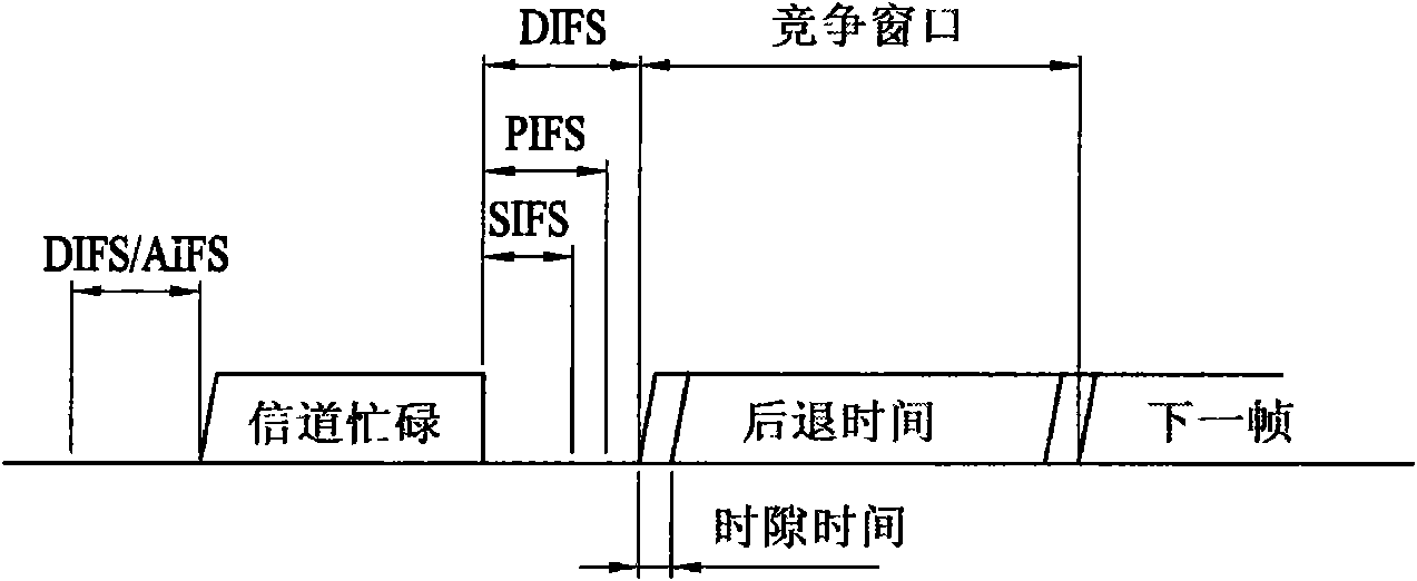
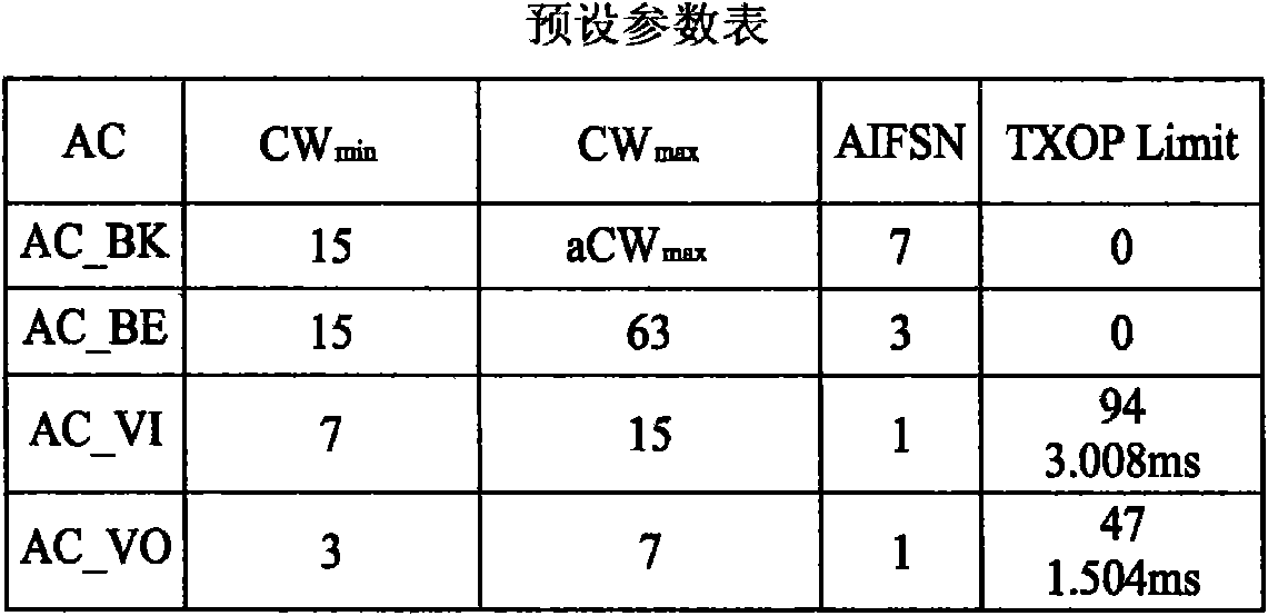
[0026] Since the availability of wireless bandwidth is limited, the management mechanism for Quality of Service (QoS) in 802.11 networks has gradually increased its importance. The IEEE 802.11e standard proposes to define QoS mechanisms for wireless devices to support bandwidth-sensitive applications, such as video and voice. The IEEE 802.11e standard defines four access types, which include AC_BK (background), AC_BE (best effort), AC_VI (video), and AC_VO (voice). Such as figure 2 As shown, these access types have different preset parameter values. The IEEE 802.11e standard uses these parameter values, such as the minimum contention window (CW min ), maximum competition window (CW max ), arbitration interframe space (AIFS) and transmission opportunity limit parameter (TXOP Limit) to ensure QoS on the wireless local area network.

[0027] In order to identify continuous noise interference, it is necessary to obtain the maximum channel busy time first. If the user sets the ac...


PUM


Abstract

The invention relates to a channel continuous noise detection method and a channel continuous noise detection device. The channel continuous noise detection device comprises a computing unit and a judging unit, wherein the computing unit is used for generating a channel busy time maximum value according to a preset parameter list; and the judging unit is used for receiving the channel busy time maximum value and a channel busy time measured value to generate a noise interference alarm.

Description

Technical field [0001] The invention relates to a channel continuous noise detection method and device, in particular to a channel continuous noise detection method and device used in the 802.11 standard. Background technique [0002] In the 802.11 standard formulated by the Institute of Electrical and Electronics Engineers (IEEE), a Distributed Coordination Function (DCF) based on Carrier Sense Multiple Access / Collision Avoidance (CSMA / CA) is formulated Mechanism to construct a wireless local area network (Wireless Local Area Network, WLAN). Using the CSMA / CA protocol, multiple workstations can share a single channel during data transmission and reduce the chance of collision. figure 1 Show an example of a workstation trying to use the DCF mechanism to access the channel. Before transmitting the frame, the workstation first checks the Received Signal Strength Indication (RSSI) value on the channel to determine whether the channel is idle. When it is detected that the channel i...

Claims


Application Information

Patent Timeline
IPC IPC(8): H04B17/00H04L12/413H04B17/345
Inventor 李明达林圣博
Owner LINK TECH INC
Why Eureka
Try Eureka