
Method and device for interference detection

A technology of interference detection and jammer, applied in the wireless field, can solve the problem of low accuracy

Active Publication Date: 2016-06-29
CHINA MOBILE COMM GRP CO LTD
View PDF5 Cites 10 Cited by
  • Summary
  • Abstract
  • Description
  • Claims
  • Application Information

AI Technical Summary

Problems solved by technology

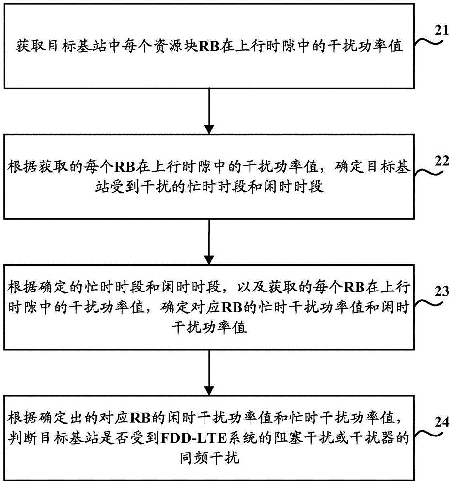
[0007] Embodiments of the present invention provide an interference detection method and device to solve the problem of low accuracy in detecting interference between systems existing in the prior art

Method used


Image

  • Method and device for interference detection
  • Method and device for interference detection
  • Method and device for interference detection

Examples


Embodiment 1

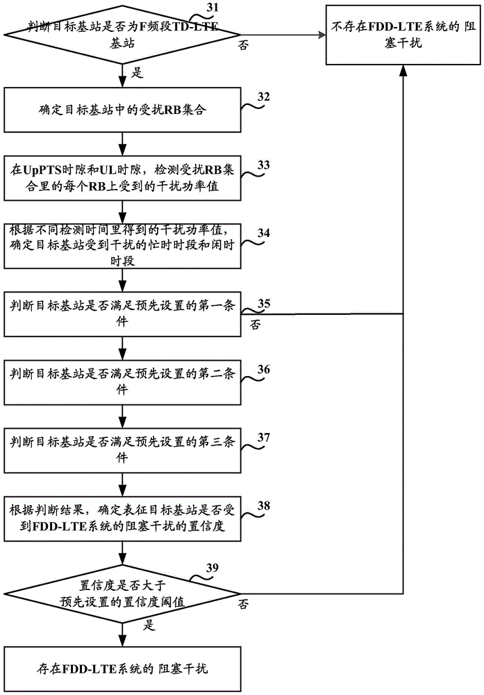
[0145] Such as image 3 As shown, it is a flow chart of a blocking interference detection method for an FDD-LTE system provided by an embodiment of the present invention, which specifically includes the following steps:

[0146] Step 31, detecting whether the target base station is a TD-LTE base station in the F frequency band.

[0147] When the detection result is yes, step 32 is performed; when the detection result is no, there is no blocking interference of the FDD-LTE system.

[0148] Step 32, determine the disturbed RB set in the target base station.

[0149] In the embodiment of the present invention, the TD-LTE system with 20M bandwidth is taken as an example. For the blocking interference of the FDD-LTE system, all 100 RBs in the TD-LTE system will be interfered. The 100 RBs in are the set of disturbed RBs.

[0150] Step 33, in the UpPTS time slot and the UL time slot, detect the interference power value received by each RB in the disturbed RB set.

[0151] This step...

Embodiment 2

[0182] Such as Figure 4 As shown, it is a flow chart of a jammer co-channel interference detection method provided by an embodiment of the present invention, which specifically includes the following steps:

[0183] Step 41, detecting whether the target base station is a TD-LTE base station in the F frequency band.

[0184] When the detection result is yes, step 32 is executed; when the detection result is no, there is no co-channel interference of the jammer.

[0185] Step 42, determine the disturbed RB set in the target base station.

[0186] In the embodiment of the present invention, the TD-LTE system with 20M bandwidth is taken as an example. For the same-frequency interference of the jammer, all 100 RBs in the TD-LTE system will be interfered. Therefore, it is determined that in the TD-LTE system, the The 100 RBs are the set of disturbed RBs.

[0187] Step 43, in the UpPTS time slot and the UL time slot, detect the interference power value received by each RB in the ...


PUM


Abstract

The invention discloses a method and a device for interference detection in order to solve the problem in the prior art that the accuracy of detecting the interference between systems is not high. The method comprises steps of obtaining an interference power value of RB of each resource block on an upstream time slot in a target base station, determining the busy time frame and idle time frame of the target base station which is interfered according to the obtained the interference power value of each RB on the upstream time slot, determining the busy time interference power value and the idle time frame interference power value of each RB according to the determined busy frame and the idle time frame and the obtained interference power value of each RB on the upstream time slot, and determining whether the base station is interfered by the blocking interference of the frequency division duplex long term evolution system and the same frequency interference of an interference unit according to the determined idle time frame interference value and the busy time frame interference power value of each RB.

Description

technical field [0001] The present invention relates to the field of wireless technology, in particular to an interference detection method and device. Background technique [0002] With the rapid development of the wireless communication market, especially the explosion of data services in recent years, the requirements for network coverage and capacity are getting higher and higher. To this end, operators have deployed a large number of wireless networks of various standards, the radius of the cell is getting smaller and smaller, and the multiplexing of antenna resources is also increasing. In this case, the noise floor of the wireless network continues to rise, and the problem of interference between systems is also becoming more and more serious. [0003] Taking the Time Division Long Term Evolution (TD-LTE) system deployed on the F-band and D-band as an example, the TD-LTE system in the F-band may be subject to intermodulation interference in the 1800 frequency band of...

Claims


Application Information

Patent Timeline
Patent Type & Authority Applications(China)
IPC IPC(8): H04W24/00
Inventor 张敏王大鹏闫渊张俪王军
Owner CHINA MOBILE COMM GRP CO LTD
Learn More