Rivet gun with improved action structure

A nail gun and action technology, which is applied in the field of pull nail guns with improved action structure, can solve the problems of overlapping or interference of driving devices, unsuitable space, long axial length of the pull nail gun, etc. force effect

Inactive Publication Date: 2011-04-06
何崇源 +1
View PDF0 Cites 5 Cited by
  • Summary
  • Abstract
  • Description
  • Claims
  • Application Information

AI Technical Summary

Problems solved by technology

[0003] However, the above-mentioned nail pullers usually cause the overall axial length of the nail puller to be too long, so it may not be suitable for places with limited space
Furthermore, if the design needs to recover the broken nail rod, some structure for recovering the nail rod is needed, and this structure will easily overlap or interfere with the driving device, which will make the structural design of the nail gun more complicated.

Method used


Image

  • Rivet gun with improved action structure
  • Rivet gun with improved action structure
  • Rivet gun with improved action structure

Examples


Embodiment Construction

[0021] The structure and effect of the present invention will be described in detail by citing the following embodiments in conjunction with the accompanying drawings.

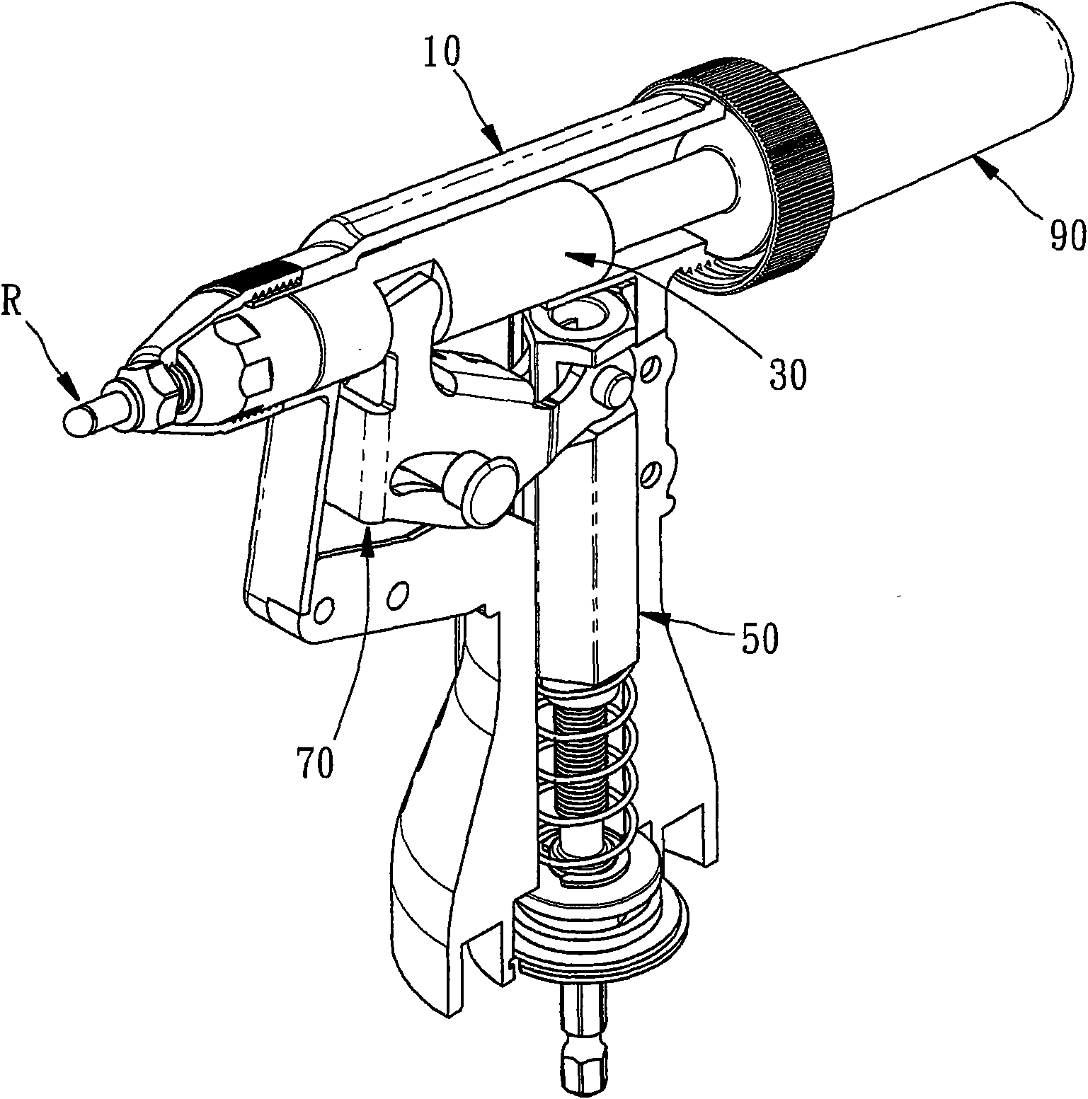
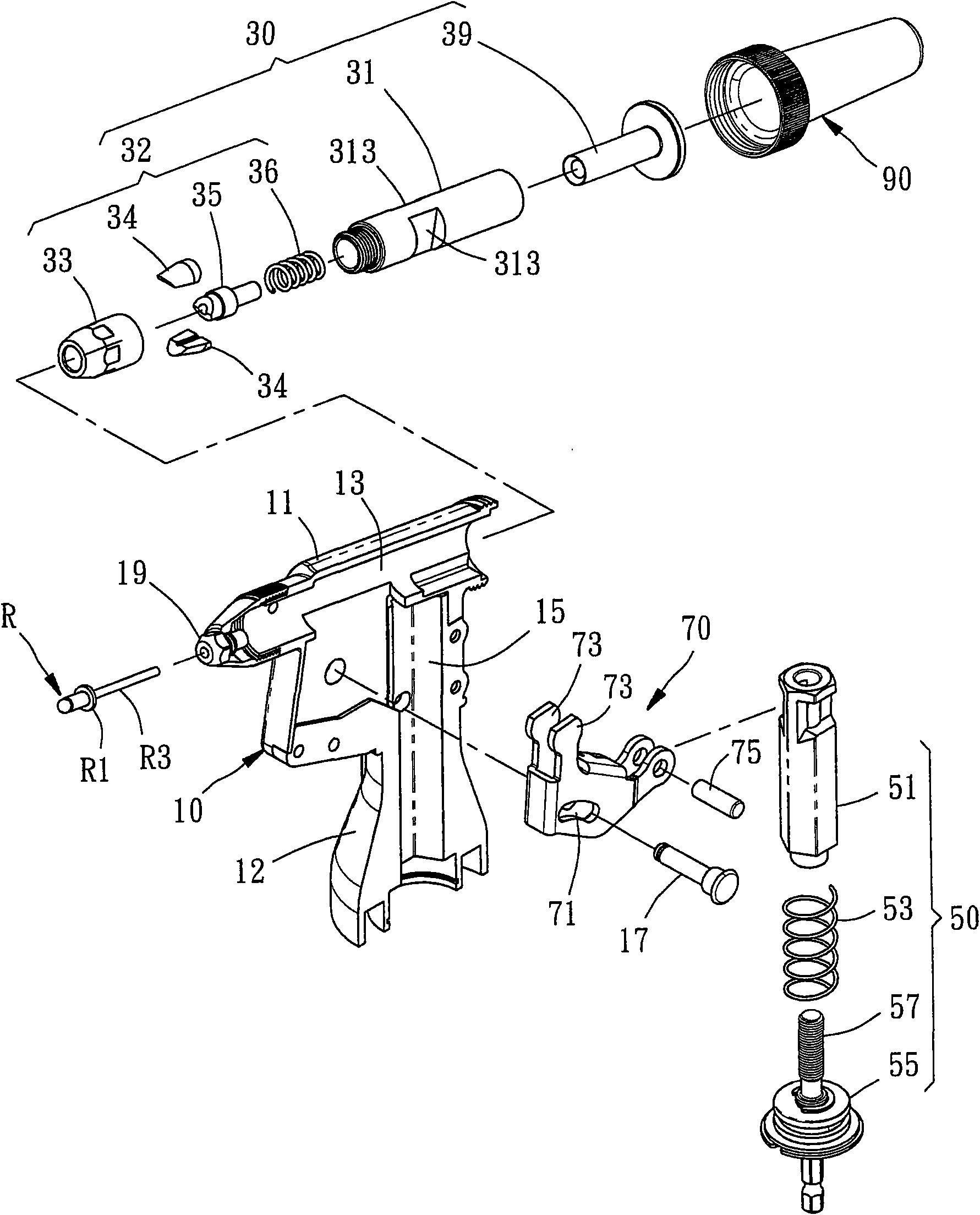
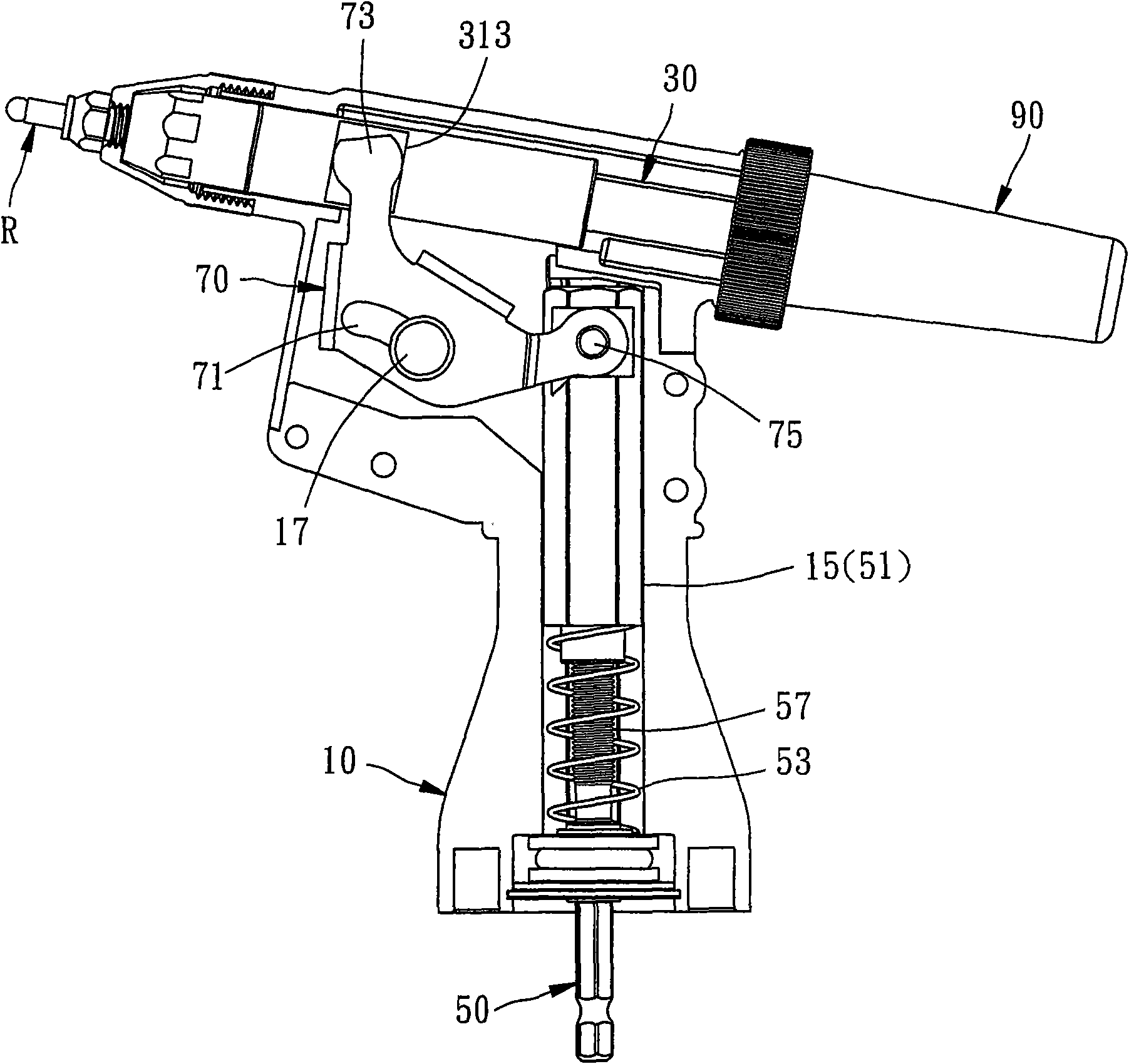
[0022] Such as Figure 1 to Figure 5 As shown, it is a rivet gun with improved action structure provided by a preferred embodiment of the present invention, which is used to pull a rivet R. The rivet R has a nail tube R1 and a nail rod R3. The rivet gun includes :

[0023] A gun group 10 has a shaft fitting part 13, a moving control fitting part 15, a moving group limiting part 17, and a nailing part 19 for installing a rivet R. Wherein the gun group 10 consists of a gun barrel 11 and a gun handle 12 connected to the gun barrel 11 at a predetermined angle, the shaft fitting part 13 is located at the gun barrel 11, and the shifting control fitting part 15 is arranged on the gun handle 12.

[0024] A pull rod group 30 has a shaft tube 31, the shaft tube 31 can be axially displaced along the shaft fitting part ...


PUM


Abstract

The invention relates to a rivet gun with an improved structure to mount a rivet which is provided with a rivet tube and a rivet bar. The rivet gun is characterized by comprising a gun group, a pull rod group, a drive group and a linking mechanism, wherein the gun group comprises an axis auxiliary part, a displacement control auxiliary part, a linking group limit part and a rivet mounting part which is used for mounting the rivet; the pull rod group is provided with an axial cylinder which is flipped along the axis auxiliary of the gun group to support against the ground to axially displace, a driven displacement part, and a clamp unit which clamps the rivet bar of the rivet; the drive group is provided with a displacement control part which can be coordinated with the motion control part to restrictedly displace; and the linking group is provided with a gun group limit part which is in slide matching with the linking group limit part of the gun group, a drive displacement part which is linked with a driven displacement part of the gun group, and a drive group pivot which is linked by the displacement control part of the drive group, so that the linking group links the pull rod group to displace relatively to deflection of the gun group. The rivet gun ensures that the space allocation of the rivet gun can be better, and gradually bigger applied force and better linking effect can be achieved.

Description

technical field [0001] The invention relates to a nail pulling device, in particular to a nail pulling gun with an improved action structure. Background technique [0002] In the known nail puller, the driving device is usually arranged at the rear end of the gun group, so that the drive of the driving device, such as the rotating part, is on the same axis as the pulling nail and the shaft cylinder, so that it can be directly driven without complicated linkage mechanism. [0003] However, the above-mentioned nail pulling guns generally cause the overall axial length of the nail pulling gun to be too long, and thus may not be suitable for places with limited space. Furthermore, if the design needs to recover the broken nail shank, some structure for recovering the nail shank is needed, which will easily overlap or interfere with the driving device, which will make the structural design of the nail puller more complicated. [0004] Therefore, the structure as described above...

Claims


Application Information

Patent Timeline
IPC IPC(8): B21J15/10B21J15/16B21J15/38
Inventor 何崇源吴政洋
Owner 何崇源
Why Eureka
Try Eureka