Supercharge Your Innovation With Domain-Expert AI Agents!

Lamp base jig

A technology of lamp pins and fixtures, applied in the direction of manufacturing tools, workpiece clamping devices, etc., can solve the problems of inconvenient operation, low efficiency, and inability to realize automation, so as to achieve the effect of improving production efficiency and increasing the degree of automation

Inactive Publication Date: 2011-04-06
周明华
View PDF7 Cites 1 Cited by
  • Summary
  • Abstract
  • Description
  • Claims
  • Application Information

AI Technical Summary

Problems solved by technology

Since the lighting lamp needs to be moved between different equipments during the welding process and sealing process, the traditional production method is to manually pack the lamp pins welded with filaments and molybdenum sheets on trays and send them to the sealing equipment. When the clip-sealing machine is working, it is manually taken out from the tray and placed on the station of the clip-sealing machine. The operation is very inconvenient, the efficiency is low, and the production automation cannot be realized.

Method used


Image

  • Lamp base jig
  • Lamp base jig
  • Lamp base jig

Examples


Embodiment Construction

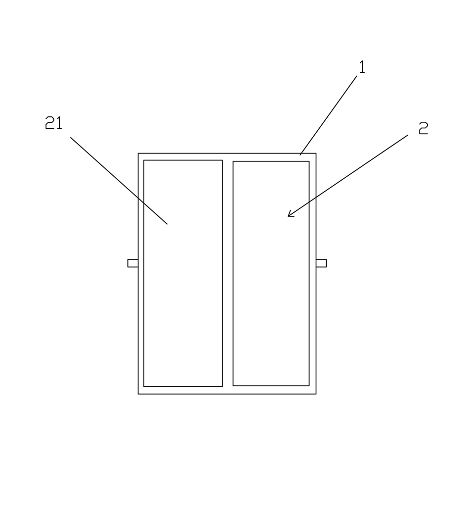
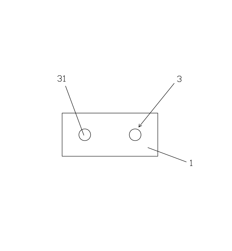
[0019] refer to figure 1 , 2 with image 3 One of the embodiments of the lamp pin fixture of the present invention includes a housing 1, a clamping mechanism 2 provided on the housing 1, an opening 3 on the side of the housing 1 for passing through the lamp pin, and the position of the clamping mechanism 2 is the same as The positions of the openings 3 are corresponding.

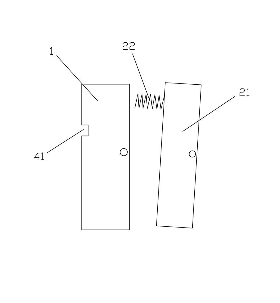
[0020] The clamping mechanism 2 includes a clamping block 21 hinged on the housing 1 , and an elastic element 22 arranged between the clamping block 21 and the housing 1 .

[0021] The elastic element 22 is a spring, and the spring is arranged on the end of the housing 1 opposite to the opening 3 . In addition, the elastic element 22 can also be a torsion spring, and the torsion spring is sleeved on the hinge shaft used to hinge the clamp block and the housing, and its two ends are respectively arranged on the inner bottom surface of the housing 1 and the bottom of the clamp block 21 . .

[0022] The op...


PUM


Abstract

The invention discloses a lamp base jig. The lamp base jig comprises a shell, a clamping mechanism and an opening, wherein the clamping mechanism is arranged on the shell; the opening used for inserting a lamp base is positioned on the side of the shell; and the clamping mechanism is opposite to the opening. After the lamp base is inserted into the jig through the opening, the clamping mechanism can clamp the lamp base tightly; the lamp base jig is arranged on equipment for producing an illuminating lamp; and from an illuminating lamp welding procedure to an illuminating lamp clamping and sealing procedure, the lamp base is driven by the lamp base jig to move, without the help of human hands, so the automation degree of the illuminating lamp production is greatly increased and the production efficiency is improved.

Description

technical field [0001] The invention relates to a lamp pin fixture, in particular to a lamp pin fixture for manufacturing lighting lamps. Background technique [0002] A common lighting lamp includes a glass shell and a lamp pin located at the lower end of the bulb, and the lamp pin is fixed to the lower end of the bulb by clamping. When manufacturing lighting lamps, it is necessary to weld the lamp pin to the molybdenum sheet first, then weld the molybdenum sheet to the filament, and then move the lamp pin with the filament and molybdenum sheet welded to the encapsulation equipment, and then perform the encapsulation process. Since the lighting lamp needs to be moved between different equipments during the welding process and sealing process, the traditional production method is to manually pack the lamp pins welded with filaments and molybdenum sheets on trays and send them to the sealing equipment. When the clip-sealing machine is working, it is manually taken out from t...

Claims


Application Information

Patent Timeline
IPC IPC(8): B25B11/00
Inventor 周明华
Owner 周明华
Features
  • R&D
  • Intellectual Property
  • Life Sciences
  • Materials
  • Tech Scout
  • Unparalleled Data Quality
  • Higher Quality Content
  • 60% Fewer Hallucinations
Learn More