Stem wave elimination device

A wave-absorbing device and bow technology, applied in the direction of hull, ship propulsion, ship parts, etc., can solve problems such as difficult to change, and achieve the effect of reducing wave resistance

Inactive Publication Date: 2011-04-06
HARBIN ENG UNIV
View PDF7 Cites 7 Cited by
  • Summary
  • Abstract
  • Description
  • Claims
  • Application Information

AI Technical Summary

Problems solved by technology

[0004] The method currently used to reduce ship resistance is mainly to optimize the ship shape, which can only

Method used


Image

  • Stem wave elimination device
  • Stem wave elimination device
  • Stem wave elimination device

Examples


Embodiment Construction

[0025] The present invention is described in more detail below in conjunction with accompanying drawing example:

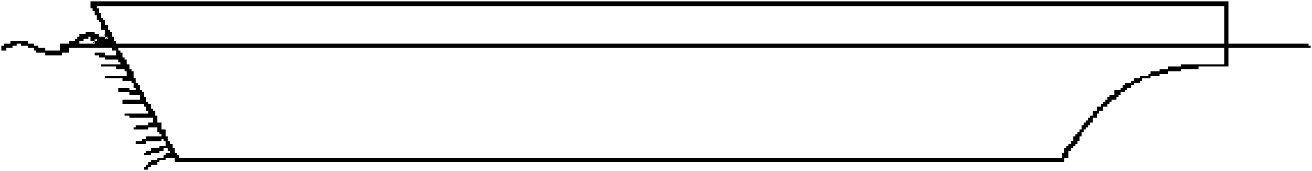
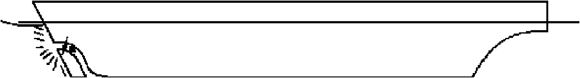
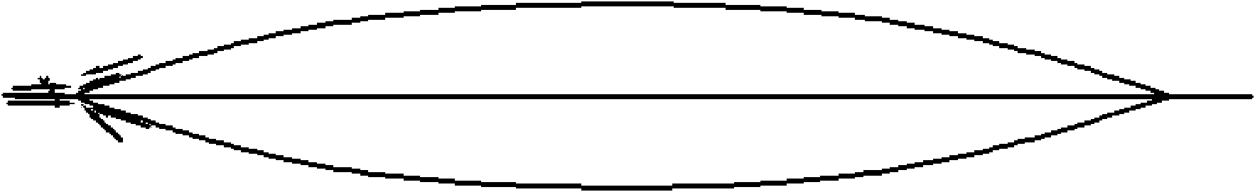
[0026] combine Figure 8 , the bow wave damping device is located at the bow of the ship, a pipeline 3 is arranged inside the bow, the angle of the entrance is horizontal, and the inside is turned to the bottom of the ship through a rounded corner; same. When the propeller is moving forward, due to the suction effect generated by the rotation of the propeller in the duct, the incoming flow in front of the ship no longer bulges and forms waves due to the propulsion of the ship, but moves quickly downward and backward along the wave dissipation device. Thus avoiding the generation of waves; due to the suction effect of the wave absorbing device, the direction of the water flow near the bow changes, and the direction of the water flow relative to the ship is the same as that of the ship itself, so the direction of friction between the hull and the water It is also ...


PUM


Abstract

The invention provides a stem wave elimination device, which comprises a pipeline arranged in the stem and a propeller arranged in the pipeline. The device of the invention can efficiently reduce wave resistance, frictional resistance and differential pressure resistance. An impeller can generate electricity by utilizing the tail flow of the propeller so as to save energy. The device can improve a finished ship and has a function of reducing the wave-making resistance, frictional resistance and sticky pressure resistance.

Description

technical field [0001] The present invention relates to a ship structure, in particular to a ship drag reduction structure, in particular to a bow wave damping device. Background technique [0002] Rapidity is one of the important performances of ships. The advantages and disadvantages of rapidity will affect the usability and economy of ships to a certain extent. The rapidity of ships includes two aspects: ship resistance and ship propulsion. Research on ship navigation The problem of resistance has a great effect on improving the rapidity of the ship. [0003] Ship resistance can be mainly divided into three parts: wave resistance, friction resistance and viscous pressure resistance. The waves generated by the ship during the movement change the pressure distribution on the surface of the hull. The resistance caused by the change of the pressure distribution caused by the waves is called the wave-making resistance. When the hull moves, due to the viscosity of the water, i...

Claims


Application Information

Patent Timeline
IPC IPC(8): B63B1/40B63H5/07
CPCY02T70/125Y02T70/10
Inventor 胡健黄胜马骋齐慧博
Owner HARBIN ENG UNIV
Why Eureka
Try Eureka