
Wheeled crane and luffing jib thereof

A jib and boom technology, applied in the field of hoisting equipment, can solve the problems of low lifting performance, increased axial force, difficulty in lifting the boom, etc. Effect

Inactive Publication Date: 2011-04-06
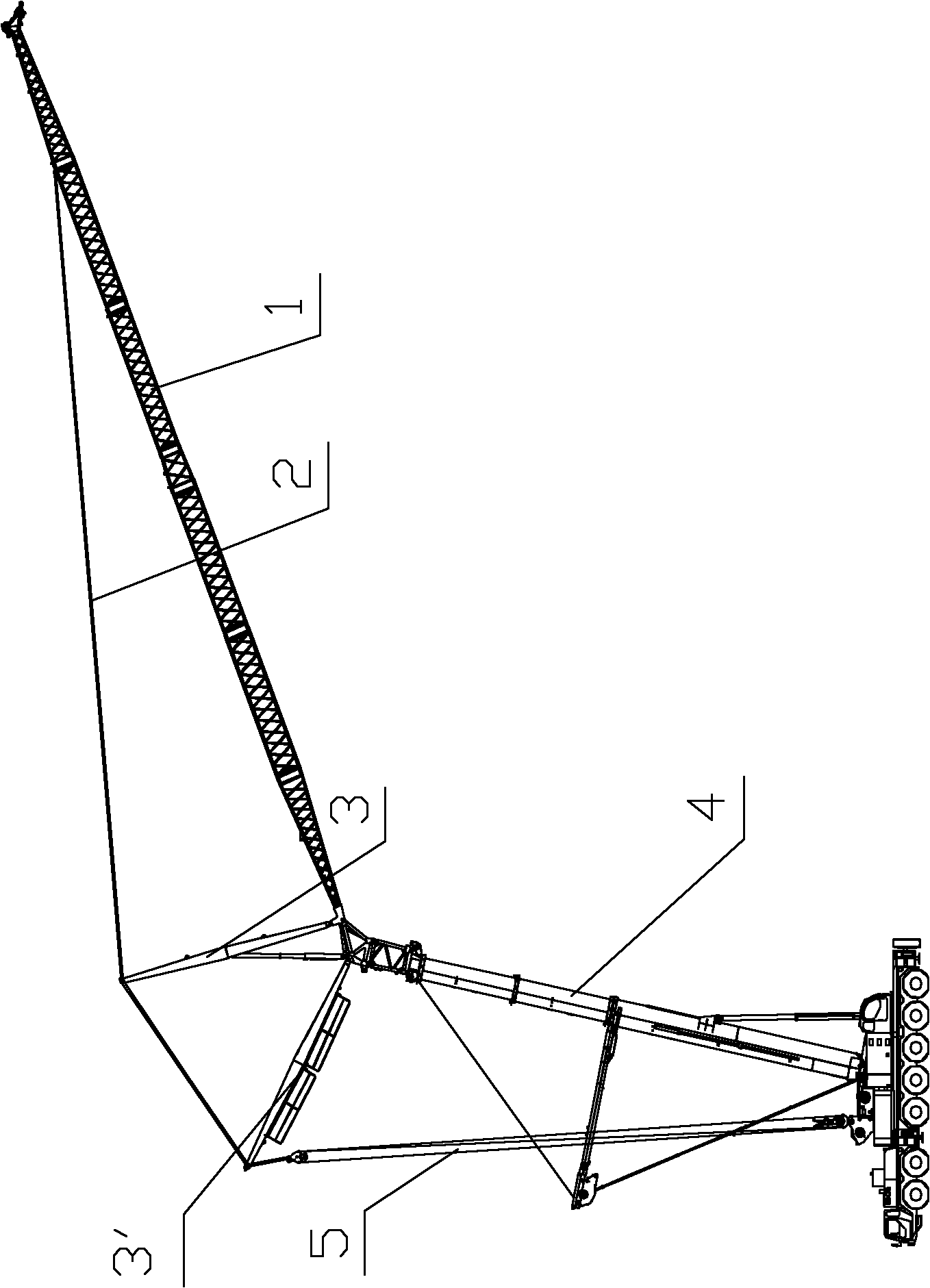
XUZHOU HEAVY MASCH CO LTD
View PDF5 Cites 10 Cited by
  • Summary
  • Abstract
  • Description
  • Claims
  • Application Information

AI Technical Summary

Problems solved by technology

[0007] In the application field of cranes, the length of the luffing jib often reaches more than 100 meters, and the weight can reach 30 tons. The deflection of the middle part of the jib under its own weight is already very large, and there is a problem of difficulty in lifting the jib; during the above operation process, After the heavy objects are hoisted at the suspended end of the jib main body 1, the jib main body 1 is similar to a simply supported beam, and the axial force it bears increases sharply, resulting in greater deflection of the jib main body 1, and its performance decreases sharply
Although the tension member 2 can reduce the length of the simply supported part, it has only one articulated point. When the length of the boom increases, the situation that the gravity deflection of the boom itself is large still cannot be changed; moreover, the articulated point of the tension member 2 is located at In the middle of the jib, the distance from the attachment point to the suspended end of the jib is still a cantilever structure, and the increase in the hoisting weight will directly increase the bending moment of the jib. Therefore, the strength of the luffing jib can only support a small amount of performance, lifting capacity limited
[0008] It can be seen that the structure of the luffing jib used in the prior art has the technical problems of large deflection, large additional bending moment after hoisting, and low lifting performance.

Method used


Image

  • Wheeled crane and luffing jib thereof
  • Wheeled crane and luffing jib thereof
  • Wheeled crane and luffing jib thereof

Examples


Embodiment Construction

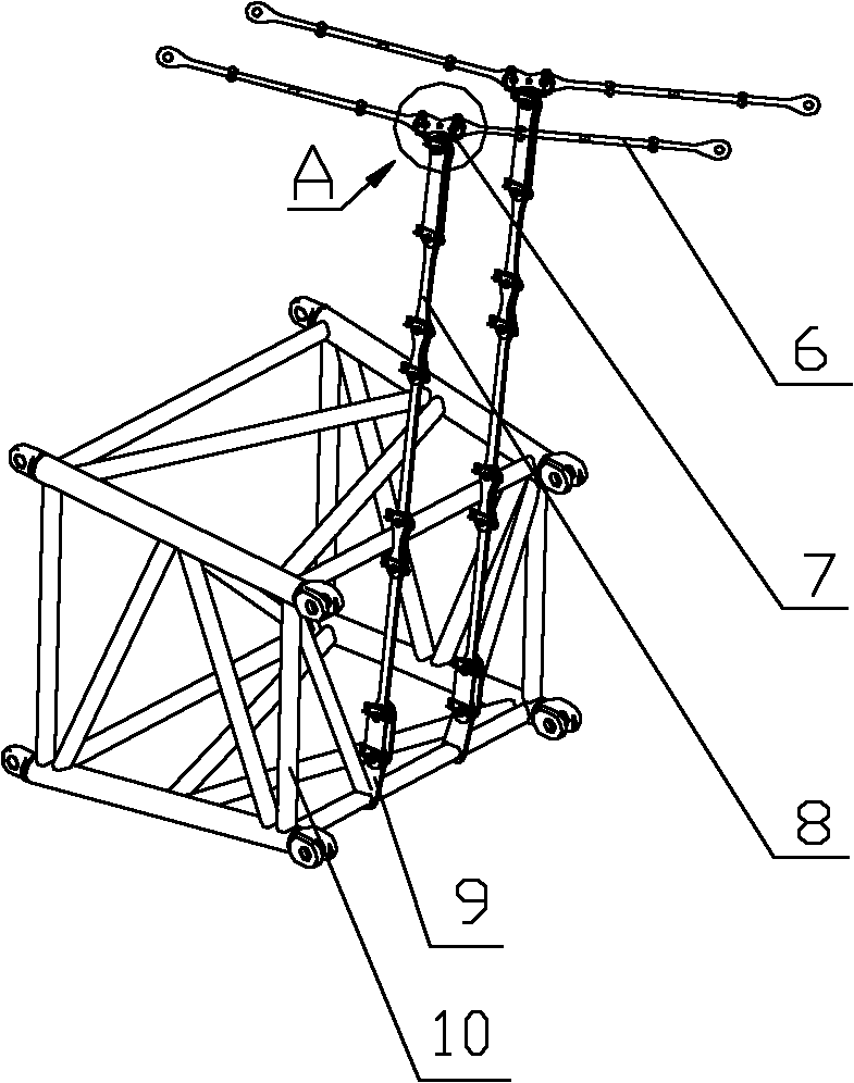
[0029] The core of the present invention is to provide a luffing jib, the luffing jib not only has small deflection itself, but also has small additional bending moment after hoisting and has high lifting performance. Another core of the present invention is to provide a wheeled crane including the above-mentioned luffing jib.

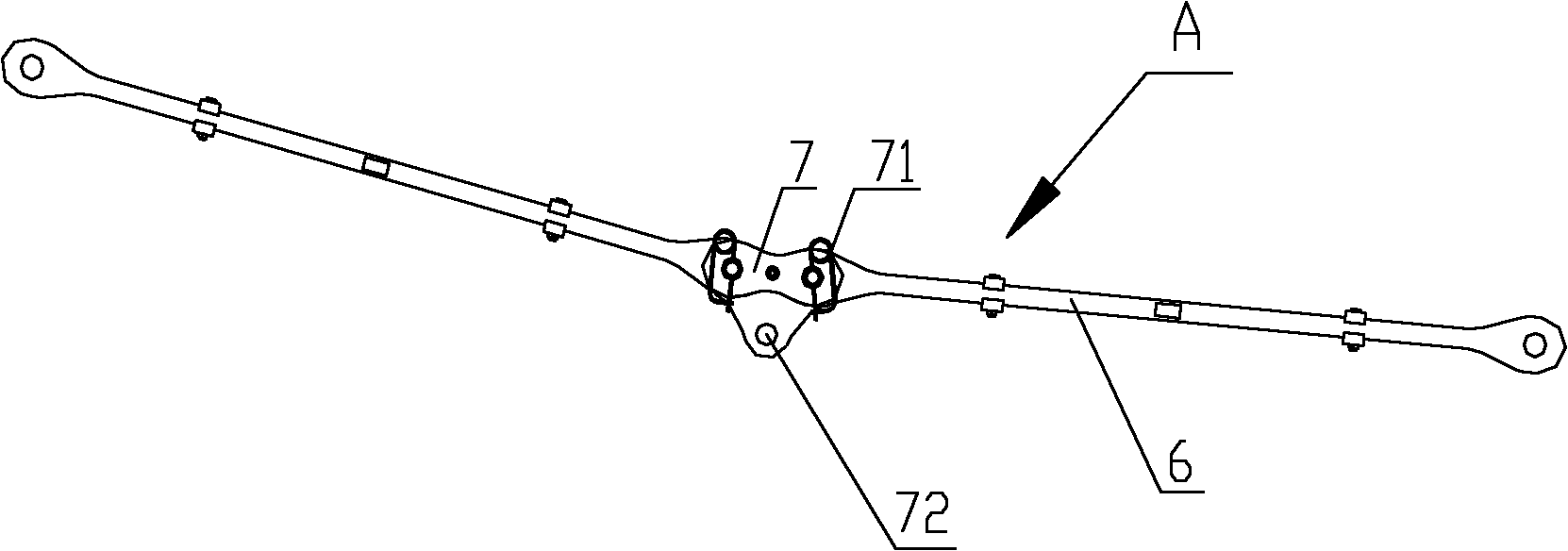
[0030] In order to enable those skilled in the art to better understand the solution of the present invention, the present invention will be further described in detail below in conjunction with the accompanying drawings and specific embodiments.

[0031] Please refer to figure 2 , figure 2 It is a partial structural schematic diagram of a specific embodiment of the luffing jib provided by the present invention.

[0032] As shown in the figure, the luffing jib includes a jib main body 10 and a tension member 6, and the end of the jib main body 10 is connected to the end of the tension member 6 ( figure 2 not shown in the figure), a first hooking ...


PUM


Abstract

The invention provides a luffing jib which comprises a jib boom main body (10), a tension device (6) and a spinal cord (8), wherein the tail end of the tension device (6) is connected with the tail end of the jib boom main body (10); a first articulating part (7) is arranged between both ends of the tension device (6); a second articulating part (9) is arranged between both ends of the jib boom main body (10); and both ends of the spinal cord (8) are respectively connected with the first articulating part (7) and the second articulating part (9). The luffing jib has the advantages of small self deflection, less additional bending moment after hoisting, and high lifting performance. The invention also provides a wheeled crane with the luffing jib.

Description

technical field [0001] The invention relates to the field of hoisting equipment, in particular to a luffing jib. In addition, the invention also relates to a wheeled crane. Background technique [0002] With the rapid development of the economy, the hoisting project is developing towards large-scale and large-scale, and the performance requirements of the cranes used in the project are getting higher and higher. [0003] In order to improve the operation performance and meet the requirements for lifting and hoisting heavy objects in large-scale engineering projects, the length and cross-section of the jib in super-large cranes are constantly increasing, especially in cranes equipped with luffing jibs, the luffing jib The length of the jib can reach more than 100 meters, and its stress form is complex. [0004] Please refer to figure 1 , figure 1 It is a structural schematic diagram of a luffing jib on a crane in the prior art. [0005] As shown in the figure, at present...

Claims


Application Information

Patent Timeline
IPC IPC(8): B66C23/64
Inventor 张正得李长青朱守法
Owner XUZHOU HEAVY MASCH CO LTD
Learn More