Locking device of box and optical fiber division box

A locking device and fiber distribution box technology, applied in the direction of fixing devices, fiber mechanical structures, mechanical equipment, etc., can solve problems such as troublesome maintenance, communication interruption, easy aging, etc., and achieve the effect of convenient maintenance and convenient direct installation

Inactive Publication Date: 2011-04-06
张家港鑫迪克电子科技有限公司
View PDF8 Cites 0 Cited by
  • Summary
  • Abstract
  • Description
  • Claims
  • Application Information

AI Technical Summary

Problems solved by technology

Because the fiber distribution box is usually placed outdoors, exposed to the sun and rain, it is very easy to age. After a period of use, the fiber distribution box needs to be replaced
At this time, it is necessary to take out the optical cable from the optical distribution tray or the splicing tray, and then reconnect it after replacing the fiber distribution box. Maintenance is very troublesome, and it will also cause communication interruption.

Method used


Image

  • Locking device of box and optical fiber division box
  • Locking device of box and optical fiber division box
  • Locking device of box and optical fiber division box

Examples


Embodiment Construction

[0023] The specific embodiments of the present invention will be described in detail below with reference to the accompanying drawings.

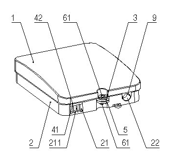
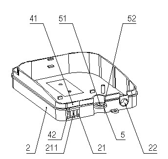
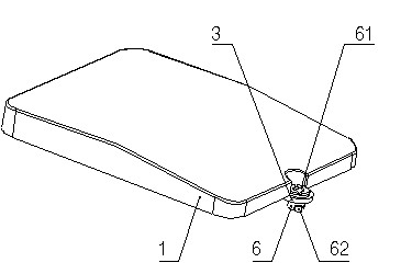
[0024] Such as figure 1 , figure 2 , image 3 As shown, the box locking device of the present invention includes a box body 2 and a box cover 1 that are snapped together. The box cover 1 is provided with a locking seat 3, and the locking seat 3 is movably provided with a locking pin. 6. The lower end of the lock pin 6 is provided with a pair of symmetrically arranged hooks 62, the side wall of the box body 2 is provided with a lock hole seat 5, and the lock hole seat 5 is provided with a pin hole 51 that matches the lock pin 6. The wall of the hole 51 is provided with a pair of guide grooves 52 corresponding to the hook 62; the lock pin 6 is provided with a padlock hole, and the end face of the pin cap 61 is also provided with a through "one" groove for easy operation .

[0025] Such as Figure 1 to Figure 4 with Image 6 As shown, the optical...


PUM


Abstract

The invention discloses a locking device of a box, and the locking device can conveniently lock up a box body and a box cover. The locking device comprises the box body and the box cover which are fastened with each other, wherein, the box cover is equipped with a locking seat; a locking pin is movably inserted into the locking seat; the lower end of the locking pin is equipped with at least one clamp hook; the side wall of the box body is equipped with a locking hole seat; the locking hole seat is equipped with a pin hole matched with the locking pin; and the wall of the pin hole is equippedwith a guide slot corresponding to the clamp hook. The invention further discloses an optical fiber division box which is provided with the locking device, an optical cable inlet and a rubber-insulated wire optical cable outlet, wherein the optical cable inlet and the rubber-insulated wire optical cable outlet are of an opening structure. The optical fiber division box is mainly used for accommodating an optical fiber connecting and forming device.

Description

Technical field [0001] The invention relates to a locking device of a box and an optical fiber splitting box used for optical fiber splicing ends. Background technique [0002] At present, the optical fiber distribution box used to place optical fiber splicing end devices such as optical distribution disks or splice trays has a structure including: a box body and a box cover that are hinged together, and the box body and the box cover are respectively provided with mutual matching The lock ring, the box body and the box cover are also provided with a matching flip cover and a flip cover seat, and the side wall of the box body is provided with an optical cable jack. When in use, after the box cover is closed, the flip cover needs to be pressed against the flip cover seat, which is troublesome to lock. In addition, when installing the optical distribution plate or splice tray, the optical cable needs to be extended from the optical cable jack into the flip box before splicing. Si...

Claims


Application Information

Patent Timeline
Patent Type & Authority Applications(China)
IPC IPC(8): G02B6/44F16B1/02
Inventor 李之尧李一品
Owner 张家港鑫迪克电子科技有限公司
Why Eureka
Try Eureka