
System power-on and power-off control device and method

An electrical control and control module technology, applied in the field of communications, can solve problems such as increasing workload and wasting manpower, and achieve the effect of reducing labor intensity and workload, and solving wasted manpower

Active Publication Date: 2011-04-06
ZTE CORP
View PDF3 Cites 3 Cited by
  • Summary
  • Abstract
  • Description
  • Claims
  • Application Information

AI Technical Summary

Problems solved by technology

[0004] The main purpose of the present invention is to provide a system power on and off control device and method to at least solve the above-mentioned problems of wasting manpower and increasing workload by using manual monitoring

Method used


Image

  • System power-on and power-off control device and method
  • System power-on and power-off control device and method
  • System power-on and power-off control device and method

Examples


Embodiment Construction

[0015] Hereinafter, the present invention will be described in detail with reference to the drawings and examples. It should be noted that, in the case of no conflict, the embodiments in the present application and the features in the embodiments can be combined with each other.

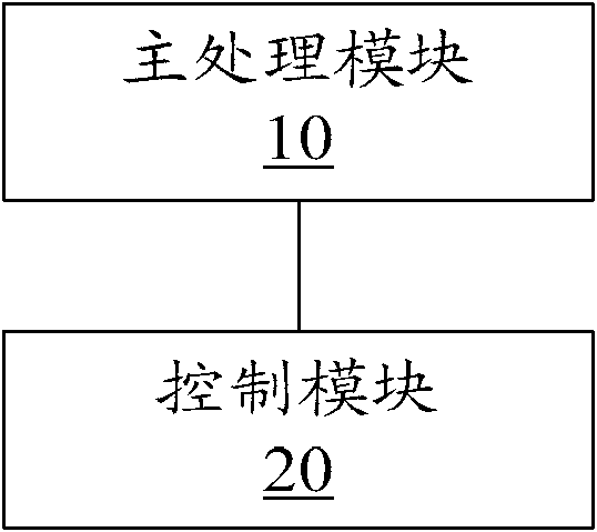
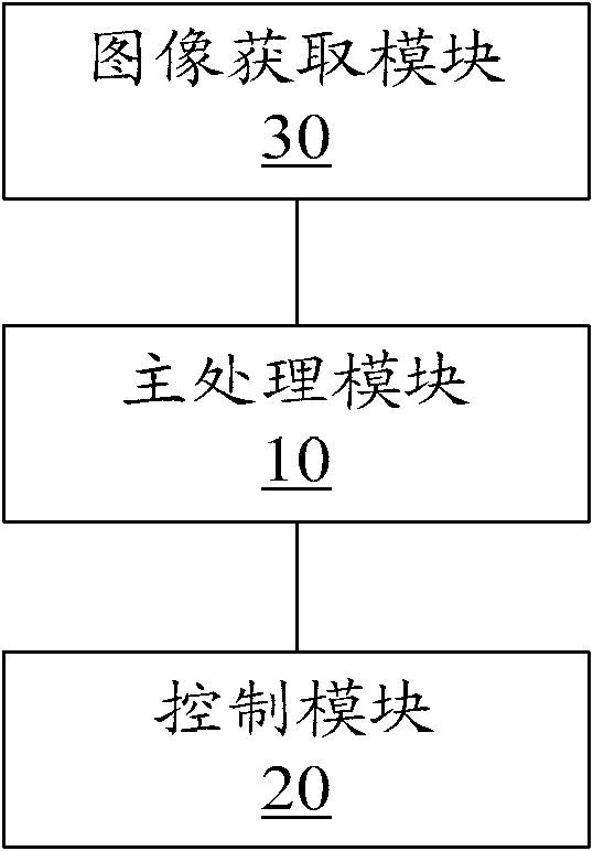
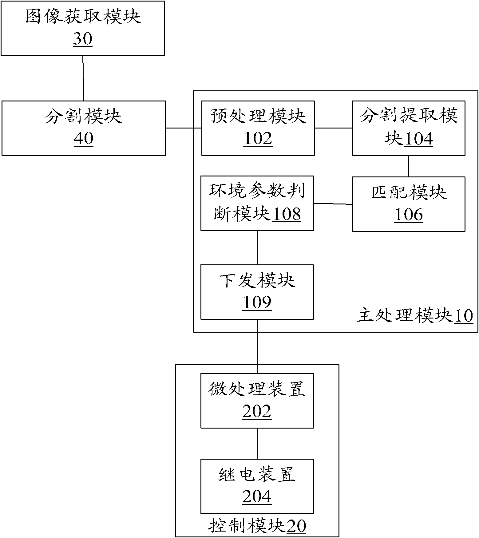
[0016] figure 1 It is a schematic diagram of a system power-on and power-on control device according to an embodiment of the present invention, including the following modules: a main processing module 10, which is used to obtain the environmental parameter value of the environment where the system is currently located, and determine whether the acquired environmental parameter value is within a predetermined environmental parameter range In addition; the control module 20 is configured to power off the control system when the judgment result of the main processing module 10 is yes.

[0017] In this embodiment, by setting the main processing module and the control module to obtain the environmental ...


PUM


Abstract

The invention discloses a system power-on and power-off control device and a system power-on and power-off control method. The system power-on and power-off control device comprises a main processing module for acquiring the environmental parameter values of the current environment of a system, and judging if the environmental parameter values go beyond preset ranges of environmental parameter values; and a control module for controlling the turning off of the power. The device and the method realize the intellectualization of the power-on and power-off control of the system and reduce labor intensity and workload for manual monitoring.

Description

technical field [0001] The present invention relates to the communication field, in particular, to a system power-on and power-off control device and method. Background technique [0002] In general, the indicators of environmental parameters may affect the working performance of the system. For example, if the temperature and humidity exceed certain upper and lower limits, the system will not work normally or even be destroyed. In this case, it is necessary to control the power-on and power-off of the system, that is, when the environmental parameters exceed the specified threshold and remain stable or have a tendency to deteriorate, the host will control the power-off of the system, and when the environmental parameters return to When within the range of the specified index and there is no repeated deterioration trend, the host computer will control the power on the system. [0003] The system generally includes an environmental measurement device capable of accurately me...

Claims


Application Information

Patent Timeline
Patent Type & Authority Applications(China)
IPC IPC(8): G06F1/26
Inventor 邱又海
Owner ZTE CORP
Learn More