
Slot turning process for stator coil and auxiliary tooling device thereof

A stator coil and groove turning technology, which is applied in the direction of prefabricated winding embedded in the motor, etc., can solve the problems of coil damage, unreliable coil insulation, difficult control of coil deformation, etc., and achieve the effect of improving reliability and avoiding damage

Active Publication Date: 2011-04-06
CSR ZHUZHOU ELECTRIC CO LTD
View PDF4 Cites 13 Cited by
  • Summary
  • Abstract
  • Description
  • Claims
  • Application Information

AI Technical Summary

Problems solved by technology

[0004] The purpose of the present invention is to overcome the problems that the deformation of the coil may be difficult to control during the stator overturning process of the existing large-diameter direct-drive wind power generator, and the coil may be easily damaged, and the coil insulation is not reliable, and to provide a method that can effectively control overturning. The deformation of the coil during the slotting process reduces the damage that the coil insulation may cause during the slotting process, and the stator coil slotting process and its tooling ensure the reliability of the slotted coil insulation

Method used

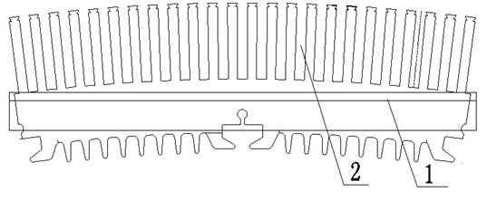
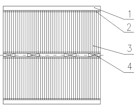
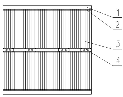

Image

  • Slot turning process for stator coil and auxiliary tooling device thereof
  • Slot turning process for stator coil and auxiliary tooling device thereof
  • Slot turning process for stator coil and auxiliary tooling device thereof

Examples


Embodiment Construction

[0011] The present invention will be further described below in conjunction with the accompanying drawings and embodiments.

[0012] The invention is a stator coil groove turning process. The expanded coil is flat-wrapped once with a white cloth tape, and the wrapping is compact. The white cloth tape is not allowed to be overlapped on the straight line, and then preformed in the groove turning mold. Then use wire rods and slot wedges to press the lower side of the coil tightly in the groove turning mold, and adjust the tightness through the pad; the lower side must be pressed tightly, otherwise the lower side will be deformed during the groove turning process. Then lift the first coil out of the core to a certain height, and the other coils are higher than the previous one by a certain distance; in the process of lifting the upper edge, force is required to be perpendicular to the core surface to provide a guarantee for the subsequent smooth insertion of the wire. When each co...


PUM


Abstract

The invention relates to a slot turning process for a stator coil and an auxiliary tooling device thereof. The process of the invention comprises the following steps: flatly wrapping a spread coil with a white cloth tape compactly once, wherein the white cloth tape is not allowed to be overlapped at a straight line edge; then preforming in a slot turning mold; compacting a lower layer edge of the coil by a coil rod and a slot wedge in the slot turning mold; then raising a first coil out of an iron core to a certain height, and raising the rest coils sequentially to be higher than the previous coil for a certain distance; in the process of raising at the upper layer edge, applying force vertical to the direction of an iron core surface for providing a guarantee for inserting the next coil smoothly; when each coil is raised, fixing a special iron rod and the upper layer edge firmly with a nylon cable tie; then raising the upper layer edge by a slot turning rod; after slot turning of the coil is finished, withdrawing the slot wedge, and taking out the coil rod and the like; when the lower layer edge of the coil is out of the slot, raising out the lower layer edge integrally by the special iron rod, wherein the straight line edge after the lower layer edge is raised out is straight without deformation; after slot turning is finished, removing the white cloth tape of the coil; wrapping outer insulation according to the insulation wrapping requirement of the coil; and normally inserting the coil as a slot turning position coil after the coil meets the requirement.

Description

technical field [0001] The invention relates to a manufacturing process and device of a motor stator, in particular to a specified sub-coil turning process and its auxiliary device turning mold. The stator coil turning process and its auxiliary device turning mold can effectively control the process of turning the groove. The amount of deformation of the coil reduces the possible damage of the coil insulation during the process of turning the groove, and ensures the reliability of the insulation of the turned coil. Background technique [0002] At present, all large-scale stator coils usually use the embedding method of stator hard windings, which can be divided into embedding method and insertion method. The multi-turn formed coil can only be embedded. When embedding to the last pitch coil, it is necessary to The upper side of the first-pitch coil raises the outer circle surface of the core, and the raised distance is based on the fact that the lower side of the last pitch ...

Claims


Application Information

Patent Timeline
Patent Type & Authority Applications(China)
IPC IPC(8): H02K15/06
Inventor 车三宏蒋炼强曹翰清李儒彬
Owner CSR ZHUZHOU ELECTRIC CO LTD
Learn More