Film tearing device and method

A film device and lamination technology, applied in packaging, transportation and packaging, unsealing of objects, etc., can solve the problems of empty welding of electronic devices and PCBA, high labor cost, product deformation, etc., to avoid hidden quality problems and reduce labor costs. , the effect of improving efficiency

Pending Publication Date: 2018-06-12
HUANWEI ELECTRONICS SHANGHAI CO LTD
View PDF0 Cites 2 Cited by
  • Summary
  • Abstract
  • Description
  • Claims
  • Application Information

AI Technical Summary

Problems solved by technology

As mentioned above, this processing method has low efficiency and high labor costs. At the same time, manual tearing of Mylar is easy to cause product deformation, which will lead to empty soldering between the electronic device and the PCBA.

Method used


Image

  • Film tearing device and method
  • Film tearing device and method
  • Film tearing device and method

Examples


Embodiment 1

[0061] This embodiment discloses a film tearing device, which is used to tear off the film material on the surface of the product.

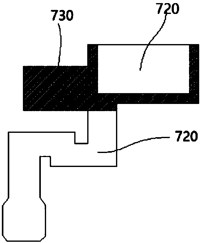
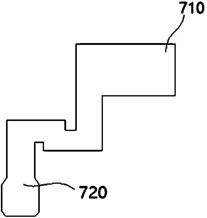
[0062] The film tearing device is a general-purpose device, not limited by product type. For convenience of description, this embodiment uses figure 1 , figure 2 The products shown in are the implementation objects, figure 1 It is a schematic diagram when there is a film material 730 on the surface of the product, the number 720 is the bare part, and the area covered with the film material 730 is the film part 710 . The schematic diagram of the product after removing the film material 730 is shown in figure 2 As shown, the film material is a general term, which generally refers to the structure that needs to be torn off on the surface of the product, which can be a film, adhesive tape or organic film material.

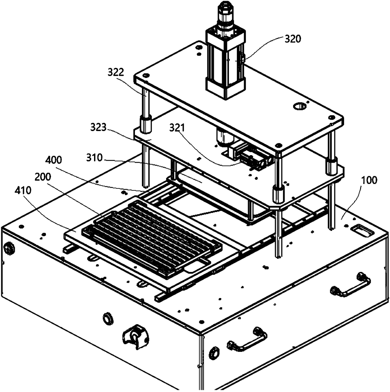
[0063] refer to image 3 , The film tearing device includes a frame 100, a tray 200, a cover plate 210 and a jaw assembly. Wherei...

Embodiment 2

[0076] Such as image 3 As shown, on the basis of Embodiment 1, the frame 100 includes a film tearing station and a discharging station, wherein the film tearing station is located below the jaw assembly, and a recycling tank 500 is also provided below the film tearing station.

[0077] The frame 100 is provided with a recovery tank 500, and the recovery tank 500 is located below the film tearing station.

[0078] The film tearing device further includes a plate-moving mechanism, which includes a fourth drive cylinder, a slide rail 400 and a tray 410. The carrier plate 200 is detachably mounted on the tray 410, and the slide rail 400 connects the film-tearing station and the discharger. position, the fourth driving cylinder drives the tray 410 to slide on the slide rail 400 . The plate moving mechanism is used to transfer the carrier tray between the film tearing station and the discharging station. The film tearing station is located under the jaw assembly to facilitate the ...


PUM


Abstract

The invention discloses a film tearing device and method. The device is used for tearing apart films on the surfaces of products, wherein the parts, covered with the films, of the products are film covered parts, and the remaining parts of the products are naked parts. The device comprises a rack, a carrying tray, a covering plate and a clamping jaw assembly, wherein the carrying tray is used forplacing the products and installed on the rack; the covering plate is arranged above the products and covers the naked parts to make the films be exposed, and the covering plate is fixedly arranged onthe carrying tray in a detachable mode; and the clamping jaw assembly is movably arranged on the rack and used for tearing apart the films on the surfaces of the products. The carrying tray is in magnetic force connection with the covering plate; and alternatively, protrusions are arranged on four sides of the carrying tray, and the covering plate is clamped on the carrying tray through the protrusions. The surface of the carrying tray is provided with through holes matched with the products in position, a vacuum base is arranged below the carrying tray, and suction nozzles of the vacuum baseare matched with the through holes in position. Film tearing efficiency is improved, and potential quality hazards caused by manual operation are avoided.

Description

technical field [0001] The invention relates to the technical field of semiconductor manufacturing process, in particular to a film tearing device and method. Background technique [0002] Tearing off the film material on the surface of the product is a common process in the semiconductor manufacturing process. The existing process generally uses manual tearing, which is inefficient and often causes product deformation due to poor manual control. [0003] For example, in order to protect the hot-melt adhesive on the surface of thin electronic devices, it is necessary to attach a layer of Mylar (polyester film) to the surface for protection. Refer to figure 1 As shown, the label 730 is the film material, and there needs to be a process of tearing the film material 730 before the operation, so that it can form figure 2 products shown in . In the prior art, the membrane material is torn off by manually operating plastic tweezers. As mentioned above, this method has low effi...

Claims


Application Information

Patent Timeline
Patent Type & Authority Applications(China)
IPC IPC(8): B65B69/00
CPCB65B69/00
Inventor 吴小强蒋明浩杨淑林
Owner HUANWEI ELECTRONICS SHANGHAI CO LTD
Why Eureka
Try Eureka