

Split solar water tank
A solar water tank and split technology, which is applied to solar thermal power generation, solar thermal devices, heating devices, etc., can solve the problems of complex production process, high production cost, low heat exchange efficiency, etc., and achieve simple production process and low production cost. , the effect of improving heat exchange efficiency
Inactive Publication Date: 2011-04-13
黄锡明
View PDF0 Cites 0 Cited by
- Summary
- Abstract
- Description
- Claims
- Application Information
AI Technical Summary
Problems solved by technology
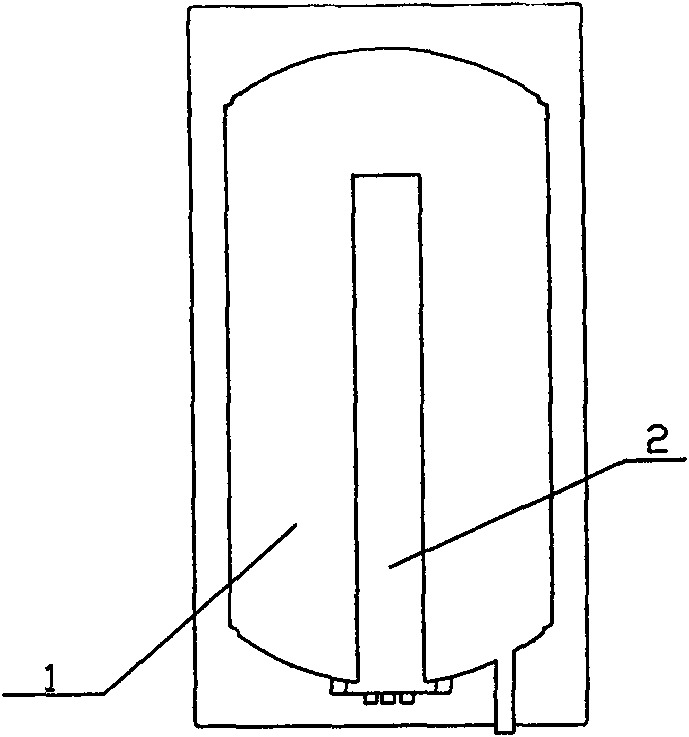
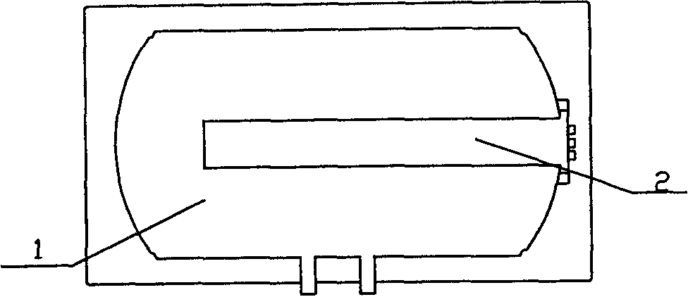
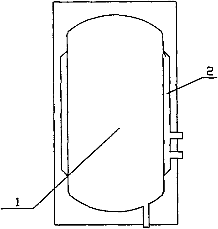
[0002] The jacket type heat exchange split solar water tank is suitable for the natural circulation and forced circulation structure installation of the split solar water heater. At present, the heat exchanger of the split solar water tank in the solar water heater is often installed in the center of its inner tank (such as figure 1 and figure 2 ) or the periphery of the liner (such as image 3 and Figure 4 ), and there is no heat exchange jacket on the outside of the semicircular head of the water tank, so the heat exchange efficiency is low, the production process is complicated, the production cost is high, and the technical requirements for installation are also high
Method used
View moreImage
Smart ImageViewing Examples

Examples
Embodiment Construction
[0012] The present invention will be further described below in conjunction with the examples. The following examples are only used to illustrate the present invention, but do not limit the present invention.
[0013] A split solar water tank, comprising an inner tank 1 and a heat exchanger 2, characterized in that the heat exchanger 2 is outside the semicircular head of the inner tank of the water tank.
[0014] Attached table: Split solar (jacket) water tank heat exchange efficiency comparison test data record table
[0015] Split solar water tank heat exchange efficiency comparison test data recording table
[0016]
Login to View More PUM
 Abstract
A split solar water tank includes an inner container (1) and a heat exchanger (2). The split solar water tank is characterized in that the heat exchanger (2) is positioned on the outside of the semicircle seal head of the water tank inner container. The invention has high heat exchange efficiency, a simple production technology, a low production cost and low requirement in installing technology.
Description
technical field [0001] The invention relates to a solar water heater, in particular to a split solar water tank. Background technique [0002] The jacket type heat exchange split solar water tank is suitable for the natural circulation and forced circulation structure installation of the split solar water heater. At present, the heat exchanger of the split solar water tank in the solar water heater is often installed in the center of its inner tank (such as figure 1 with figure 2 ) or the periphery of the liner (such as image 3 with Figure 4 ), and there is no heat exchange jacket on the outside of the semicircular head of the water tank, so the heat exchange efficiency is low, the production process is complicated, the production cost is high, and the technical requirements for installation are also high. Contents of the invention [0003] The technical problem to be solved by the invention is to provide a split solar water tank with high heat exchange efficiency, s...
Claims
Login to View More Application Information
Patent Timeline
 Patent Type & Authority Applications(China)
IPC IPC(8): F24J2/46
CPCY02E10/40
Inventor 黄锡明
Owner 黄锡明