Method and device for jointly and synchronously measuring velocity/pressure during pitching/rolling movement of model

A technology of pitch motion and synchronous measurement, used in the aerospace field

Inactive Publication Date: 2011-04-13
BEIHANG UNIV
View PDF0 Cites 24 Cited by
  • Summary
  • Abstract
  • Description
  • Claims
  • Application Information

AI Technical Summary

Problems solved by technology

[0006] At present, it has not been seen at home and abroad. Under the dynamic roll / pitch two-degree-of-freedom motion of the model, the joint and synchronous measurement of the motion of the model, the measurement of object surface pressure and the space velocity field precedent

Method used


Image

  • Method and device for jointly and synchronously measuring velocity/pressure during pitching/rolling movement of model
  • Method and device for jointly and synchronously measuring velocity/pressure during pitching/rolling movement of model
  • Method and device for jointly and synchronously measuring velocity/pressure during pitching/rolling movement of model

Examples


Embodiment Construction

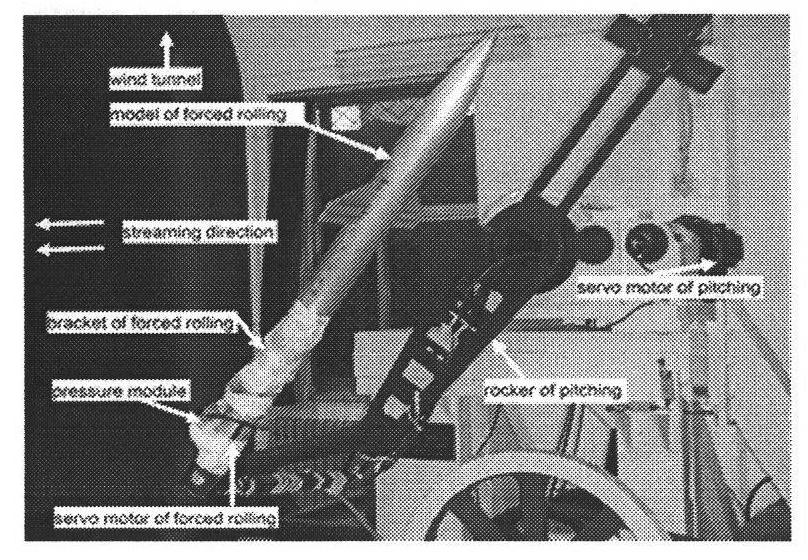
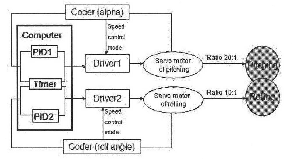
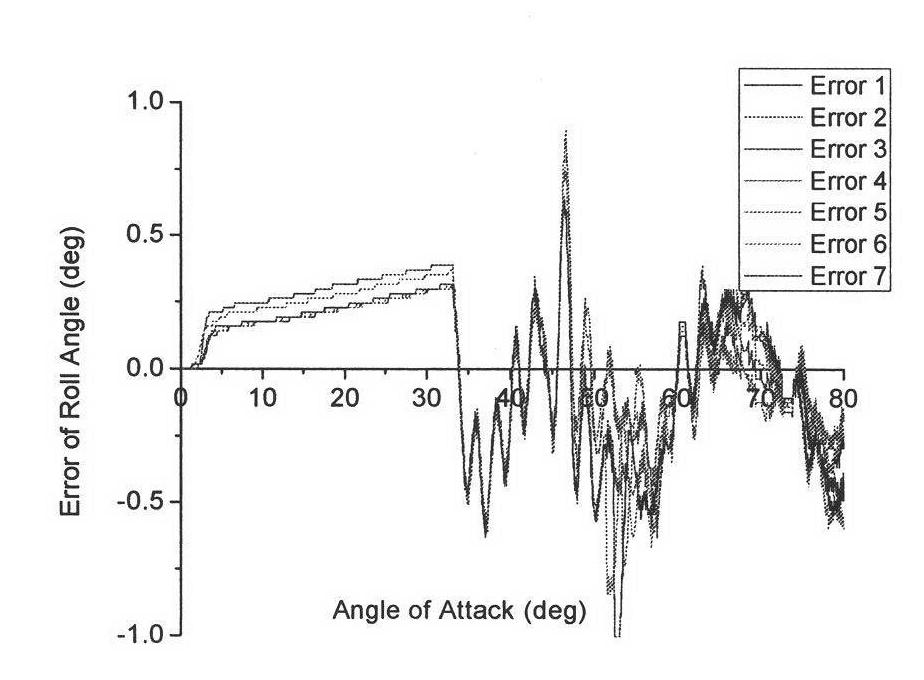
[0027] The invention is to carry out synchronous measurement on the motion time history, surface pressure and PIV of the model in the pitch / rock two-degree-of-freedom motion. Figure 1 shows an example of a mechanism that can achieve a given law of pitch-rock motion and its system control diagram. It can be seen from the figure that the pitch and rock motions are driven by two servo motors respectively, and the motors are controlled by the PID closed-loop control method Carry out the simulation movement, two kinds of simulation movements use the same timer, and the simulation movement can achieve higher precision by adjusting the appropriate PID parameters, as shown in Figure 2.

[0028] For the dynamic surface pressure measurement of the model, the scanning valve pressure measurement system is adopted. The multi-point pressure measurement on the model surface is carried out by punching pressure measurement holes on the model surface. The pressure measurement holes are connected...


PUM


Abstract

The invention relates to an experiment method for jointly and synchronously measuring model motion track, object plane pressure and space velocity field during pitching-rolling two-degree-of-freedom dynamic simulation motion control process. A pitching motion mechanism and a model support rod are simultaneously driven through an industrial personal computer to respectively drive the model to make pitching and rolling motion along preset tracks. When the model moves to a position requiring data acquisition, the industrial personal computer sends an instruction to pressure measuring equipment and PIV (Particle Image Velocimetry) equipment at multiple points, and the actual motion position, the object plane pressure and the space velocity field of the model are collected synchronously. Experiment results show that two-degree-of-freedom coupled simulation motion has high precision under the control of PID (Proportion Integration Differentiation) closed loop feedback, and the error of synchronous measurement can be reduced by transmitting an external trigger signal of synchronous measurement according to a partitioning method. The joint and synchronous experiment technology provides an effective research means for the analysis of the large angle-of-attack unsteady flow mechanism.

Description

technical field [0001] The invention relates to a wind tunnel experiment method in the field of aerospace, in particular to a method for joint measurement of model movement and various flow quantities during model dynamic pitch / two-degree-of-freedom movement. Background technique [0002] Modern fighter jets usually require large angle of attack maneuvering flight to improve their combat effectiveness. This maneuvering flight action is usually achieved by flying fast pitch and roll, and at the same time, uncontrollable non-stop motion will also occur when flying at a large angle of attack. Linear flight motions such as wing rocking in limit cycle oscillations around the body axis. Therefore, it is of great engineering significance to study the aerodynamic characteristics and flow field characteristics of fighter jets when they are pitching, laterally rolling or oscillating coupled motion. [0003] Under the condition of large angle of attack, affected by flow phenomena such...

Claims


Application Information

Patent Timeline
Patent Type & Authority Applications(China)
IPC IPC(8): G01M9/06
Inventor 马宝峰邓学蓥徐思文王延奎李岩
Owner BEIHANG UNIV
Why Eureka
Try Eureka