Test device for measuring thrust of shock tunnel
A test device, shock wave wind tunnel technology, applied in the direction of measuring device, aerodynamic test, machine/structural component test, etc., can solve the problem of high strength requirements of the test section, achieve saving production costs, improve adaptability, and overall Simple and reasonable structure
- Summary
- Abstract
- Description
- Claims
- Application Information
AI Technical Summary
Problems solved by technology
Method used
Image
Examples
Embodiment 1
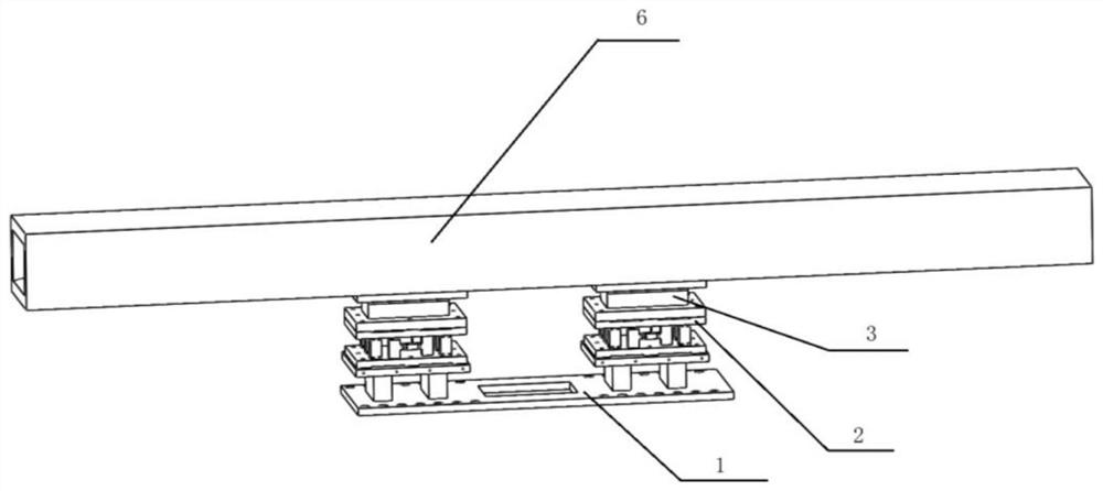
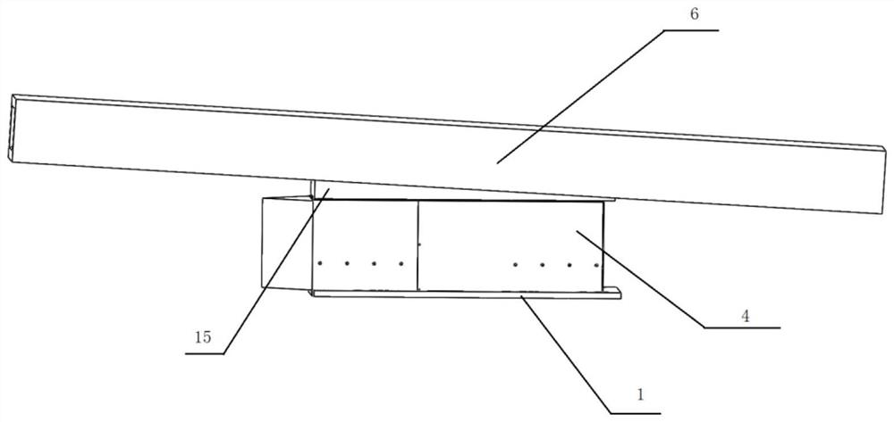
[0035] In this embodiment, a shock tunnel thrust measurement test device such as Figure 1-2 As shown, it includes a support base 1 , a balance 2 , a model balance adapter 3 , a fairing 4 and an accelerometer 5 .
[0036] Such as Figure 7 As shown, the support base 1 includes a base plate 17 and two balance mounting bases 16 fixedly mounted on the base plate 17, and a set of balances 2 is mounted on each balance mounting base 16. The bottom plate 17 is an integral rectangular structure. The two balance mounts 16 are arranged in parallel along the length direction of the bottom plate 17 (that is, the length direction of the model). The balance mounting base 16 is composed of two main bodies and a mounting panel in a rectangular parallelepiped structure. The bottom plate 17 is fixedly connected with the angle-of-attack mechanism of the wind tunnel by means of screw connection.
[0037] Such as Figure 4-5As shown, the balance 2 includes an upper connection plate 7 , a lowe...
Embodiment 2
[0043] In this embodiment, a shock tunnel thrust measurement test device such as image 3 As shown, it includes a support base 1 , a balance 2 , a model balance adapter 3 , a fairing 4 , an accelerometer 5 and an angle wedge 15 .
[0044] Such as Figure 7 As shown, the support base 1 includes a base plate 17 and two balance mounting bases 16 fixedly mounted on the base plate 17, and a set of balances 2 is mounted on each balance mounting base 16. The bottom plate 17 is an integral rectangular structure. The two balance mounts 16 are arranged in parallel along the length direction of the bottom plate 17 (that is, the length direction of the model). The balance mounting base 16 is composed of two main bodies and a mounting panel in a rectangular parallelepiped structure. The bottom plate 17 is fixedly connected with the angle-of-attack mechanism of the wind tunnel by means of screw connection.
[0045] Such as Figure 4-5 As shown, the balance 2 includes an upper connectio...
Embodiment 3
[0051] In this embodiment, a shock tunnel thrust measurement test device such as Figure 1-2 As shown, it includes a support base 1 , a balance 2 , a model balance adapter 3 , a fairing 4 and an accelerometer 5 .
[0052] Such as Figure 10 As shown, the support base 1 includes a base plate 17 and two balance mounting bases 16 fixedly mounted on the base plate 17, and a set of balances 2 is mounted on each balance mounting base 16. The bottom plate 17 is a split structure composed of the bottom plate I and the bottom plate II, and the two balance mounting seats 16 are installed on the bottom plate I and the bottom plate II respectively. The two balance mounts 16 are arranged in parallel along the length direction of the bottom plate 17 . The balance mounting base 16 is composed of two main bodies and a mounting panel in a rectangular parallelepiped structure. The bottom plate I and the bottom plate II are fixedly connected with the angle of attack mechanism of the wind tunn...
PUM
 Abstract
Description
Claims
Application Information
 - R&D
- Intellectual Property
- Life Sciences
- Materials
- Tech Scout
- Unparalleled Data Quality
- Higher Quality Content
- 60% Fewer Hallucinations
Browse by: Latest US Patents, China's latest patents, Technical Efficacy Thesaurus, Application Domain, Technology Topic, Popular Technical Reports.
© 2025 PatSnap. All rights reserved.Legal|Privacy policy|Modern Slavery Act Transparency Statement|Sitemap|About US| Contact US: help@patsnap.com


