Timer

A mechanical timer and housing technology, which is applied to time program switches, electrical components, electrical switches, etc., can solve the problems of unreasonable structure of timer inserts, frequent replacement, unclear timing information, and shortened service life. Eliminates risk of breakage, consistent diameter, enhanced service life

Inactive Publication Date: 2011-04-13
孙利云
View PDF4 Cites 4 Cited by
  • Summary
  • Abstract
  • Description
  • Claims
  • Application Information

AI Technical Summary

Problems solved by technology

[0005] In order to solve the problems of shortened service life, frequent replacement and unclear timing information in the prior art due to the unreasonable structure of the inserting piece of the timer, the present invention provides a timer with a reasonable structure, clear timing position and not easy to damage

Method used


Image

  • Timer
  • Timer
  • Timer

Examples


Embodiment Construction

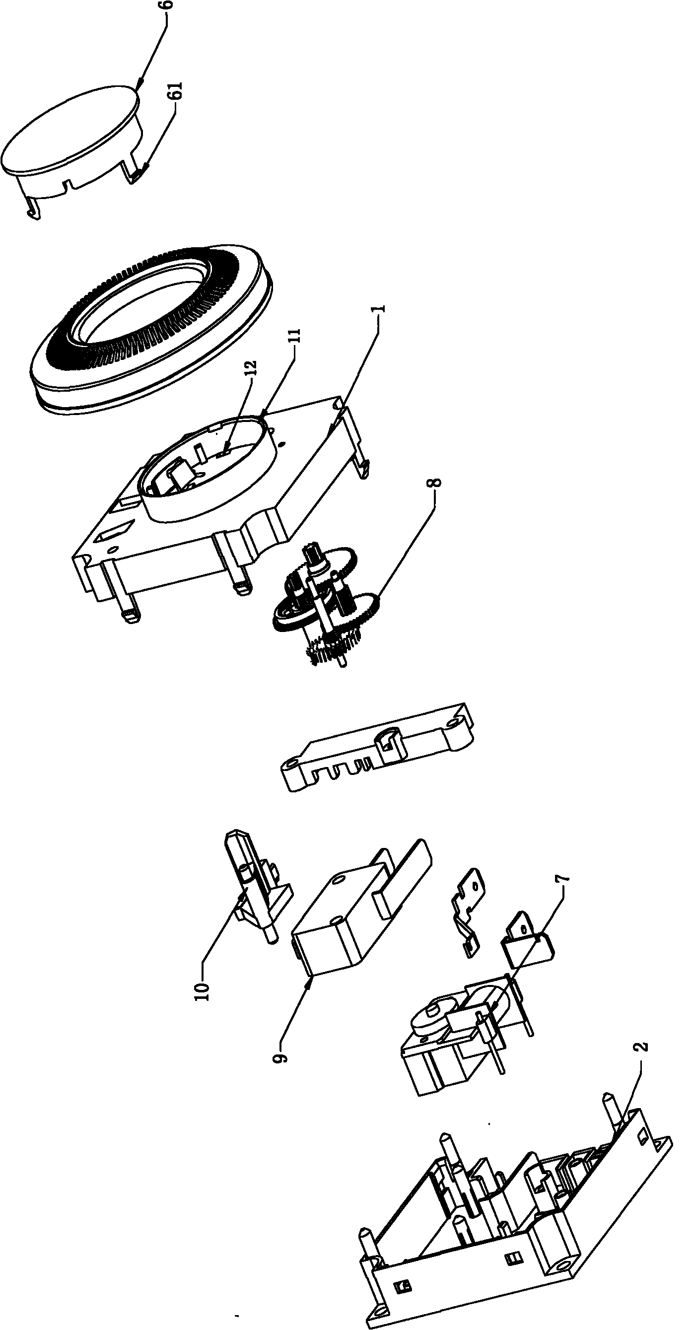
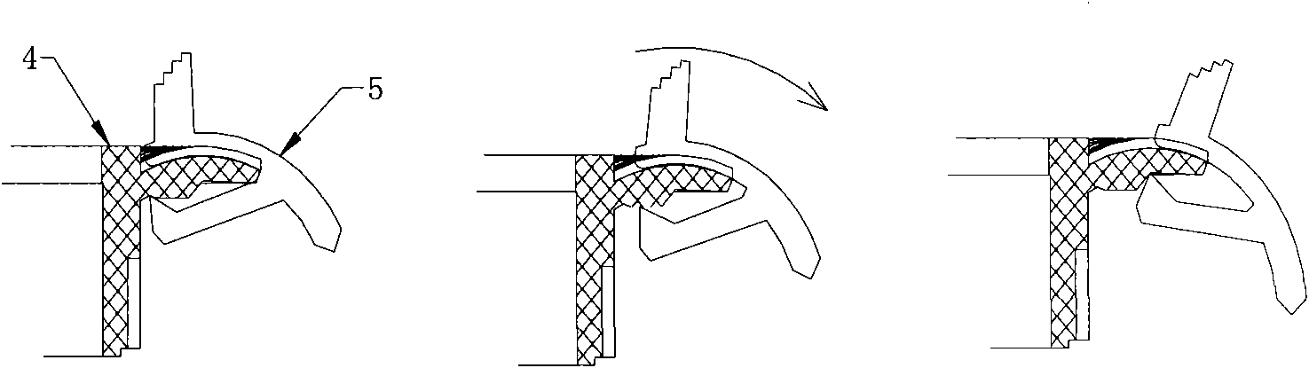
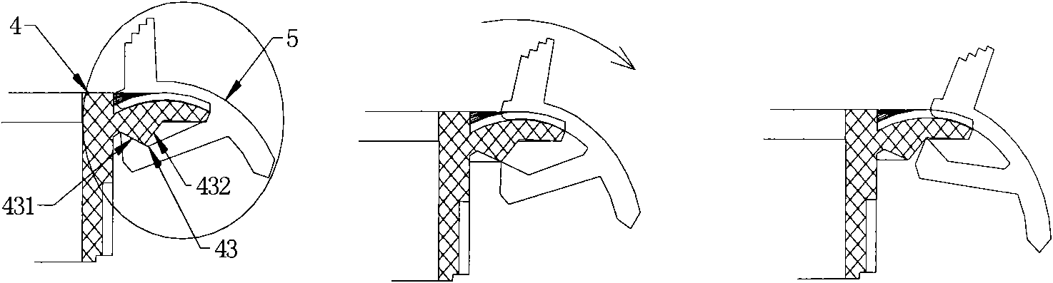
[0030] Such as figure 1 , 5 , 6, 7, and 9, the upper casing 1 and the lower casing 2 form a hollow box body for installing timing components, the power part and transmission mechanism of the timer are installed in the box body, and the timing setting device is installed in the box body. On the outer surface of the body, the timing setting device includes a scale circle 3 , an index circle 4 , an insert piece 5 and an indicator circle 6 . The scale ring 3 and the index ring 4 are in the shape of a dome with an inner hole in the center. The scale ring 3 is sleeved in the inner hole cylinder 41 of the index ring from top to bottom through the extended cylinder 31 of the inner hole. The inner hole of the index ring 4 The lower end of the hole cylinder 41 is plugged into the protruding cylinder 11 on the surface of the upper housing 1, and the indicator ring 6 is installed in the inner hole of the scale ring 3, and is stuck on the protruding cylinder 11 of the upper housing by a ...


PUM


Abstract

The present invention discloses a timer, specifically relates to a timing device capable of realizing controls of corresponding time interval according to needs, comprising a box body, a gear transmission system, a synchronous motor, a micro switch, a cradle, a scale circle, a graduated circle, wherein a plurality of inserting sheets is disposed outer circumference of the graduated circle; the scale circle is disposed at the upper surface of the graduated circle; strip empty slots with a position and a number corresponding to the position and the number of the inserting sheets are radially disposed at the surface of the graduated circle; fixed bulges are disposed at top ends of blocking edges of the inserting sheet; a circle of radially fixed ledges is disposed at the lower surface of the graduated circle; the top end for locating the bulge and the fixed ledge is a tip angle; the inserting sheets are blocked at the inner side of the fixed ledges by the fixed bulges and fixed on the graduated circle. The timer of the present invention uses the principle that the friction between tip angles are small to amplify the elasticity effect of the inserting sheet, and realize the fast location of the inserting sheet.

Description

technical field [0001] The invention relates to a timing device, in particular to a timing device capable of controlling corresponding time periods as required. Background technique [0002] In people's daily life, it is often necessary to stipulate that a certain device should run for a specified time, or start working at a specified time. Some of the above effects are controlled by software programs. This type of control requires more complex equipment and processing centers, and The program needs to monitor until the condition is met. There are also some short-term timing devices realized by pure mechanical devices. The length of time selected by manual control, the timing device will disconnect or turn on the corresponding device after reaching the predetermined time. This type of timing device has simple structure, low cost, easy operation and low error rate. Low, currently used in most home appliances and equipment. Such as timing control on microwave ovens, water di...

Claims


Application Information

Patent Timeline
Patent Type & Authority Applications(China)
IPC IPC(8): H01H43/10
Inventor 孙利云
Owner 孙利云
Why Eureka
Try Eureka