Floating connector

A technology of floating connectors and connectors, which is applied in the direction of connection, parts of connection devices, electrical components, etc., can solve the problems of damaged plug connectors, loose connection of plugs and sockets, etc., and achieve the effect of reliable connection

Active Publication Date: 2011-04-13
NANJING KANGNI TECH IND +1
View PDF6 Cites 24 Cited by
  • Summary
  • Abstract
  • Description
  • Claims
  • Application Information

AI Technical Summary

Problems solved by technology

[0003] In a power station or in a car, the connection between the plug and the socket may be displaced due to vibration or other uncertain factors. Since the plug and the socket are re

Method used


Image

  • Floating connector
  • Floating connector
  • Floating connector

Examples


Embodiment Construction

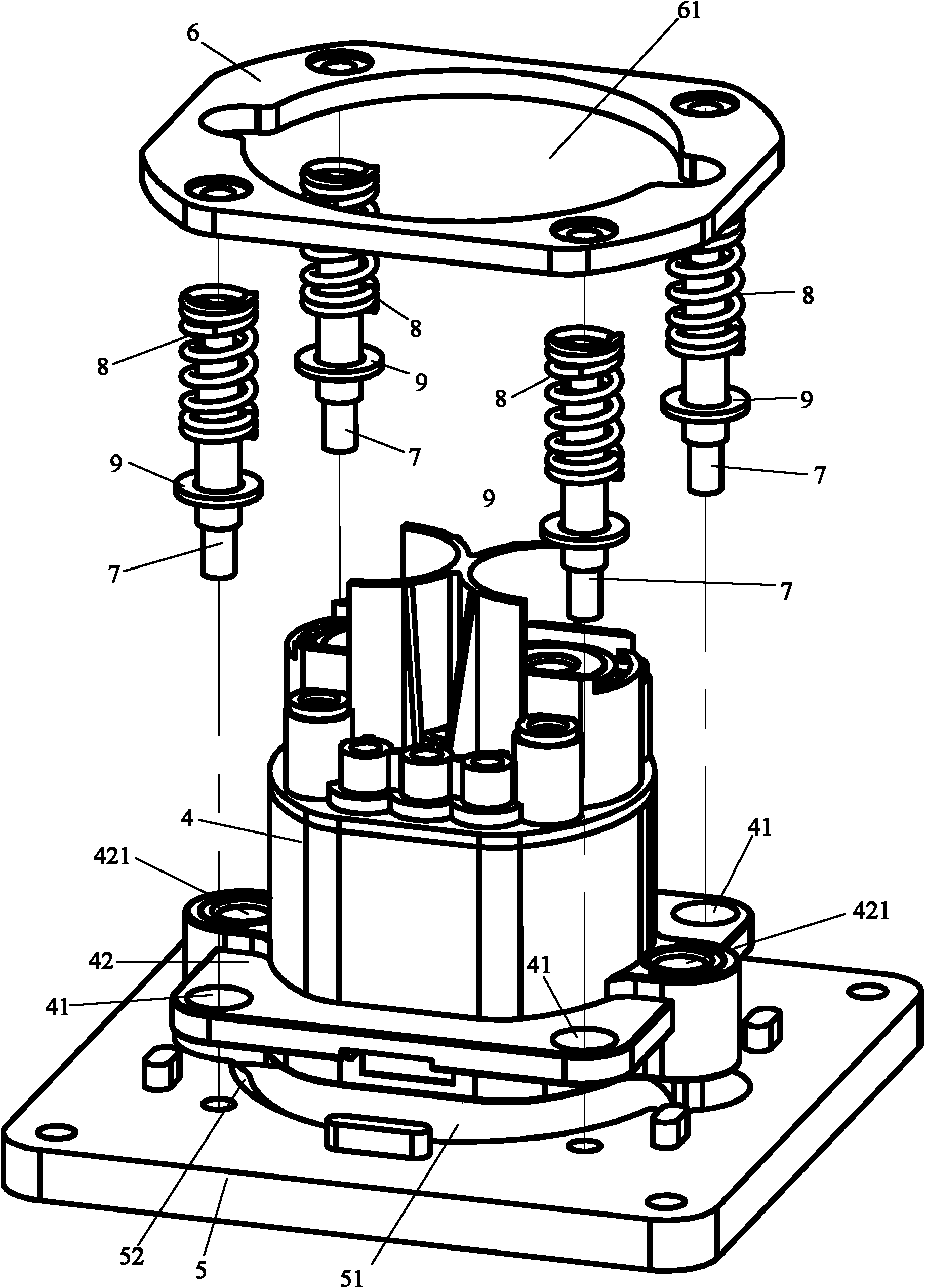
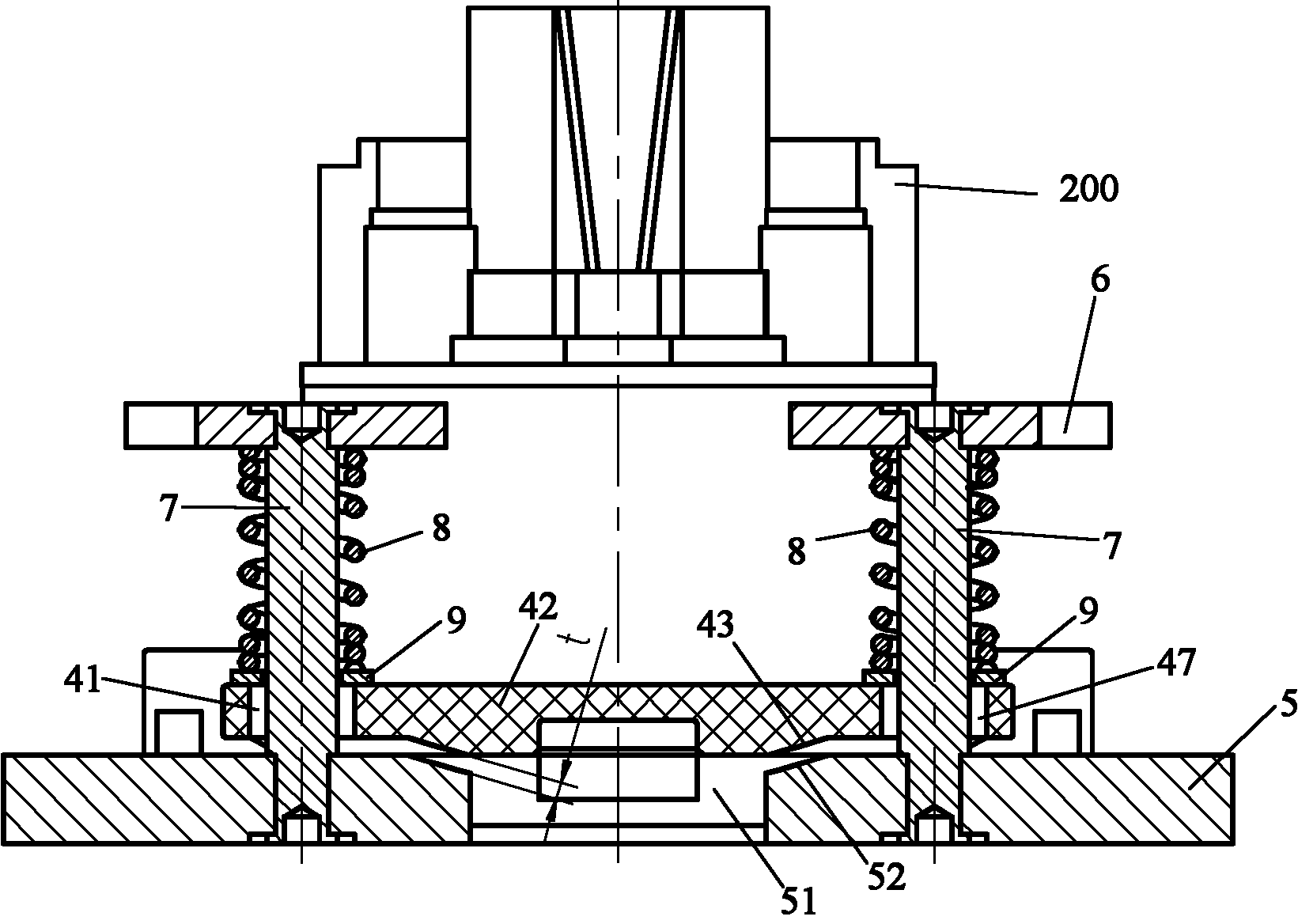
[0018] see Figure 1-6 As shown, the floating connector of the present invention includes two parts: a plug 100 and a floating receptacle 200 .

[0019] The plug 100 includes a plug body 1 , a flange 2 fixed on the plug body (the flange 2 may be integrated with the plug body), and two guide pins 3 fixed on the flange 2 . The guide pin has a tapered tip 31 .

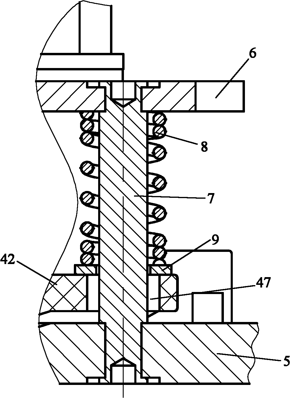
[0020] The floating socket 200 includes a socket body 4 , a front fixing plate 5 , a rear fixing plate 6 , four fixing shafts (riveting shafts) 7 , and four cylindrical helical compression springs 8 .

[0021] The socket body 4 and the plug body 1 belong to the existing structure, and they are pluggably connected to form a connector.

[0022] The front fixing plate 5 is an annular plate having a central hole 51, and the rear fixing plate 6 is also an annular plate having a central hole 61.

[0023] The axis of the socket body 4 (the pluggable direction, the axis of the connector) coincides with the axes of the central ...


PUM


Abstract

The invention provides a floating connector having X, Y, Z axial displacements. The floating connector can ensure that two connector clips can be reliably connected in the inserting process and under the vibration condition. The floating connector comprises at least one connector clip in a connector consisting of the two connector clips which can be inserted and pulled out, and also comprises a front fixed plate and a rear fixed plate which are fixed at both ends of a fixed shaft; the axial direction of the fixed shaft is parallel to the direction of inserting and pulling out the connector; the fixed shaft passes through a floating hole formed on a shell of one connector clip; a gap is reserved between the floating hole and the fixed shaft; and an elastic element which can ensure that theconnector clip is contacted with the front fixed plate in an ordinary state is arranged between the connector clip with the floating hole and the rear fixed plate.

Description

technical field [0001] The invention relates to a floating connector which can still be reliably connected in a vibrating state and has displacement requirements in X, Y and Z directions. Background technique [0002] A connector generally consists of two inserts that can be plugged and connected. A connector composed of two inserts, a plug and a socket, is a common connector. At present, with the advancement of the charging car project, a charging car that replaces the battery box is gradually gaining popularity. Accumulator is housed in the storage battery case, and fixed socket is housed on the storage battery case. A plug corresponding to the socket is fixed on the automobile, and the plug is connected with the socket to supply power to the automobile during use. After the battery power in the battery box is exhausted, the battery box can be taken off from the car and charged at the battery changing station. When charging, the socket on the storage battery box will be...

Claims


Application Information

Patent Timeline
IPC IPC(8): H01R13/631
Inventor 沈兵朱金大施淼森倪峰丁丽张浩
Owner NANJING KANGNI TECH IND
Why Eureka
Try Eureka