BOOST circuit with short circuit protection function

A short-circuit protection circuit and short-circuit protection technology, applied in the electronic field, can solve problems such as increasing costs, and achieve the effects of simple circuit structure, strong economy and practicability

Active Publication Date: 2011-04-13
HASCO VISION TECHNOLOGY CO LTD
View PDF2 Cites 19 Cited by
  • Summary
  • Abstract
  • Description
  • Claims
  • Application Information

AI Technical Summary

Problems solved by technology

[0004] In the design of BOOST circuits, especially some small and medium power BOOST cont

Method used


Image

  • BOOST circuit with short circuit protection function
  • BOOST circuit with short circuit protection function

Examples


Embodiment

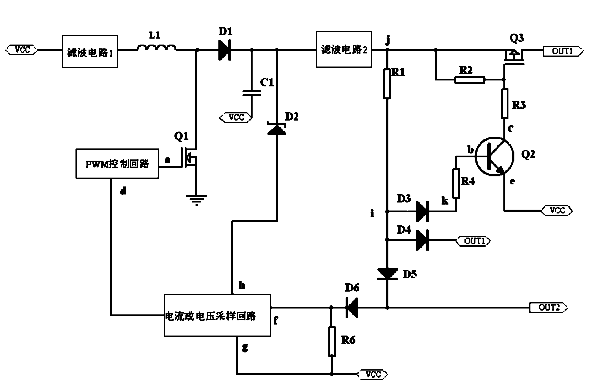
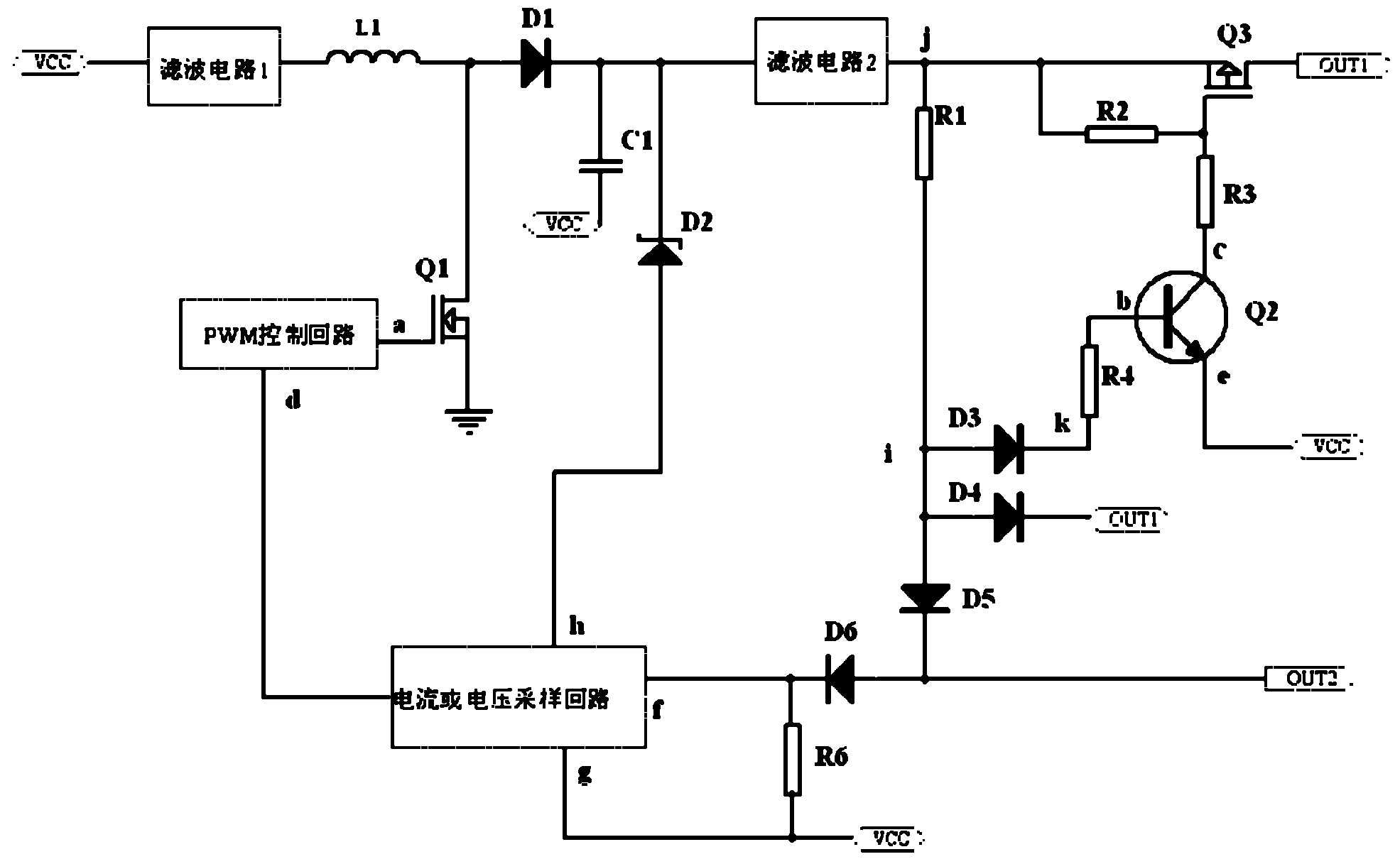
[0015] Such as figure 1 Shown is a circuit block diagram of the BOOST circuit of the present invention. The BOOST circuit includes a power supply VCC, an output terminal OUT, a BOOST circuit module, a current or voltage sampling loop module and a short circuit protection circuit module, the input terminal of the BOOST circuit module is connected to the power supply VCC, and its output terminal is connected to the second Zener diode The negative pole of D2 is connected to the short-circuit protection circuit module, the positive pole of the second Zener diode D2 is connected to one end of the current or voltage sampling loop module, and the other end of the current or voltage sampling loop module is connected to the sixth resistor R6. One end is connected, and the other end of the sixth resistor R6 is connected to the power supply VCC. Wherein, the current or voltage sampling loop module can sample the load current and voltage, and after comparing with the reference voltage Vc...


PUM


Abstract

The invention discloses a BOOST circuit with a short circuit protection function, comprising a volt current condenser (VCC), an output end (OUT), a BOOST circuit module, a current or voltage sampling circuit module and a short circuit protection circuit module, wherein the input end of the BOOST circuit module is connected with the VCC, and the output end of the BOOST circuit module is connected with the negative pole of a second voltage regulator diode D2 and the short circuit protection circuit module; the positive pole of the second voltage regulator diode D2 is connected with one end of the current or voltage sampling circuit module; and the other end of the current or voltage sampling circuit module is connected with one end of a sixth resistance R6; and the other end of the sixth resistance R6 is connected with the VCC. By adopting the short circuit protection circuit in the BOOST circuit, the short circuit protection of an output port to a power supply and the earth can be realized under an open circuit state or a load state, and the normal work can be restored without electrification once again after fault removal.

Description

technical field [0001] The present invention relates to the field of electronic technology, in particular to a BOOST circuit (switching DC boost circuit, its characteristic is that its output voltage can be higher than the input voltage) with short-circuit protection function, which is especially suitable for applications based on power boost In the BOOST circuit. Background technique [0002] In the standard BOOST circuit, since there is no switching device in the main circuit from the power supply to the output circuit, once a short circuit occurs, it is irresistible. In many examples, a switching device will be connected in series from the power supply to the output circuit in the BOOST circuit, and the output circuit current will be detected through a micro-control system and a dedicated chip, and then the switch of the switching device will be controlled. The cost of doing so will be relatively high. Moreover, the protection control depends on the main control circuit ...

Claims


Application Information

Patent Timeline
IPC IPC(8): H02M3/155H02H7/10H02H3/06
Inventor 夏盛
Owner HASCO VISION TECHNOLOGY CO LTD
Why Eureka
Try Eureka