Strap joint rotator with pivoting linkage and pinch wheel

A technology of strapping and joints, which is applied to the parts and packaging of strapping machinery, and can solve the problems of small shape and affecting the size of strapping machines.

Inactive Publication Date: 2011-04-13
PREMARK PACKAGING LLC
View PDF3 Cites 6 Cited by
  • Summary
  • Abstract
  • Description
  • Claims
  • Application Information

AI Technical Summary

Problems solved by technology

More desirably, such strap joint rotators have a sufficiently small profile to minimally, if ever, affect the size of the strapping machine.

Method used


Image

  • Strap joint rotator with pivoting linkage and pinch wheel
  • Strap joint rotator with pivoting linkage and pinch wheel
  • Strap joint rotator with pivoting linkage and pinch wheel

Examples


Embodiment Construction

[0028] Although the present invention can have embodiments in various forms, what will be described in the accompanying drawings and below is a current preferred embodiment, and it should be understood that what is currently disclosed is an example of the present invention and by no means It is intended that the invention be limited to the specific embodiments described.

[0029] It should also be understood that the heading of this section of the specification, "Detailed Description of the Invention," refers to the requirements of the US Patent Office and does not imply, nor should it be inferred, that limitations on the subject matter disclosed herein are intended.

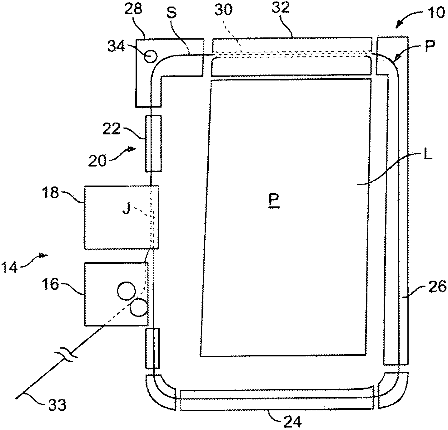
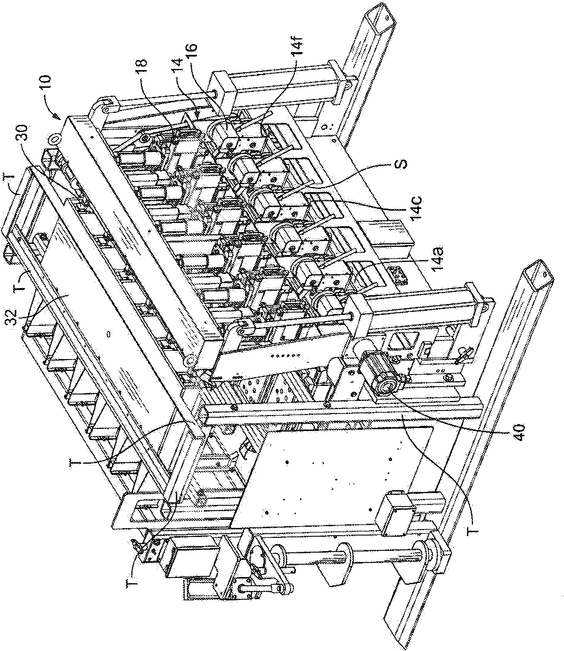
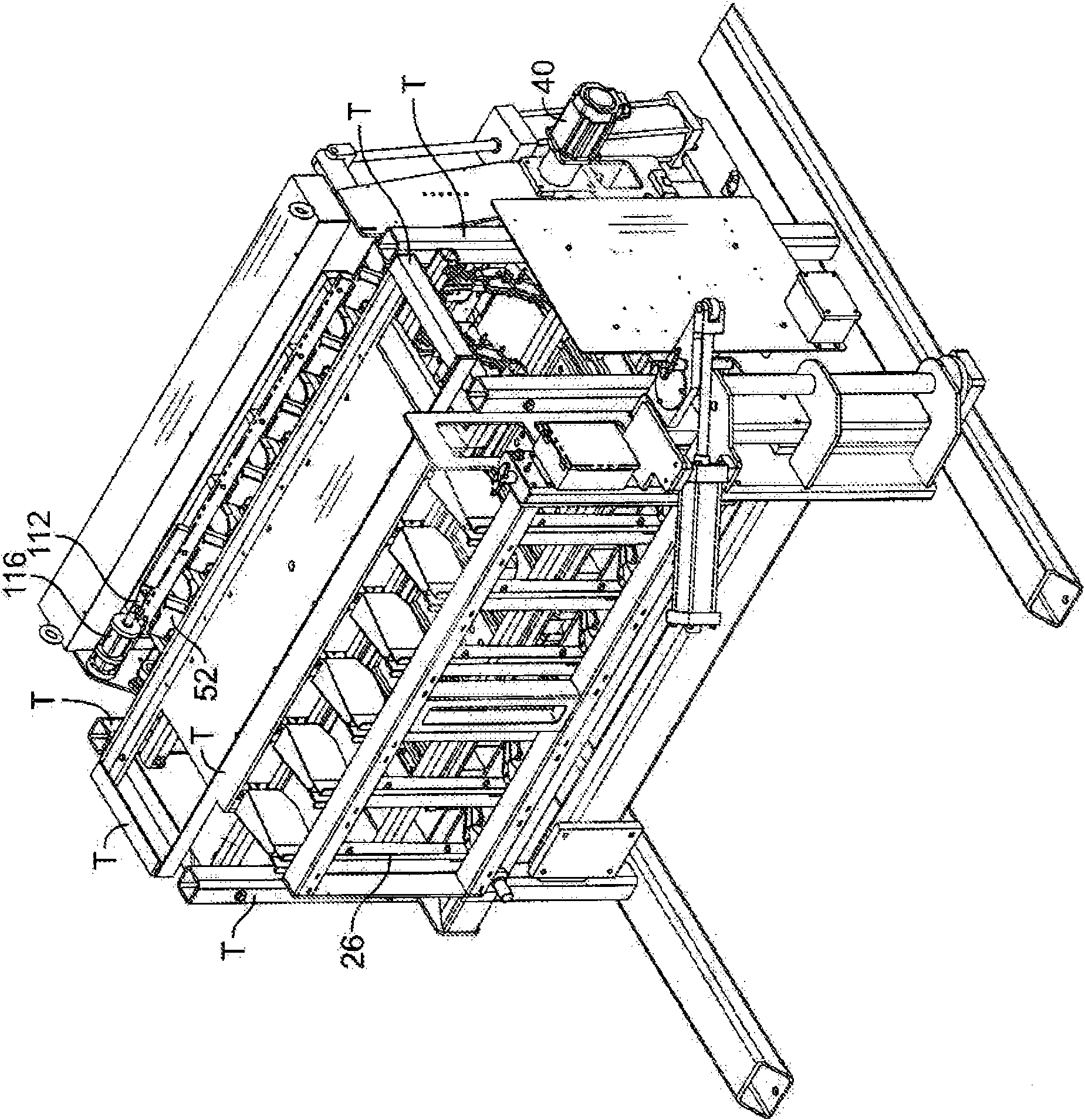
[0030] Referring to the accompanying drawings, especially figure 1 , shows a strapping machine 10 having a pivoting pinch wheel strap rotator 12 in accordance with the principles of the present invention for use with compressible materials. The illustrated strapping machine 10 includes six separate but interdep...


PUM


Abstract

A strap joint rotating assembly (12) is for use with a strapping machine (10) of the type for feeding a strapping material (5) around a load (L), positioning, tensioning and sealing the strapping material around the load. The strapping machine has a feed head (16) for feeding the strapping material into the strapping machine, a strap chute (20) through which the strapping material is passed and a sealing head (18) to seal overlapping courses of the strapping material to one another to define a strap loop having a seal and defining a strap loop plane (Pp). The strap traverses from the feed head, through the strap chute and sealing head to define a strap path (P). The strap joint rotating assembly includes a driven wheel (34) having an axis of rotation generally perpendicular to the strap loop plane and a pinch wheel (36) that has an axis of rotation (A36) and is carried on a wheel block (60). The wheel block pivots to move the pinch wheel into and out of the strap loop plane. The pinch wheel, when in the strap loop plane, has its axis of rotation parallel to the axis of rotation of the driven wheel. The pinch wheel is further movable toward the driven wheel to pinch the strap (S) between the driven wheel and the pinch wheel. The driven wheel is driven to rotate the strap loop around the load. A strapping machine having a strap joint rotator is also disclosed.

Description

technical field [0001] The invention relates to a rotator for a binding joint. More specifically, the present invention relates to a strap joint rotator for use with a strapping machine for compressible materials, the strap joint rotator having a strap pivoting tie rod and a pinch wheel. Background technique [0002] Strapping machines are well known for securing straps around compressible goods such as cotton bales or other textile materials. In order to properly contain the bales, multiple straps are often used, eg, fed around the load, tensioned and sealed to create a packed load. Typically, such bales are strapped with plastic strapping material. [0003] The strapping machine adapted to the bale has a frame on which the various strapping components are mounted. Several separate but associated feeding and sealing or strapping heads, strap chutes and other components for placing straps around the load are mounted on the frame. The strapping units operate in relation t...

Claims


Application Information

Patent Timeline
Patent Type & Authority Applications(China)
IPC IPC(8): B65B13/20B65B27/12
CPCB65B13/20B65B27/12
Inventor 拉塞尔·M.·弗劳姆达里尔·M.·迪瓦恩罗伊·J.·詹森韦斯利·P.·诺瓦克斯基理查德·G.·纽曼
Owner PREMARK PACKAGING LLC
Why Eureka
Try Eureka