Oldham's coupling screw compressor with gap

A technology of coupling and clearance, used in couplings, elastic couplings, rotary piston machines, etc., can solve problems such as loud noise and overload

Inactive Publication Date: 2002-12-18
EMERSON CLIMATE TECH INC
View PDF3 Cites 2 Cited by
  • Summary
  • Abstract
  • Description
  • Claims
  • Application Information

AI Technical Summary

Problems solved by technology

This engagement of the keys in the slots overloads the keys and produces excessive noise

Method used


Image

  • Oldham's coupling screw compressor with gap
  • Oldham's coupling screw compressor with gap
  • Oldham's coupling screw compressor with gap

Examples


Embodiment Construction

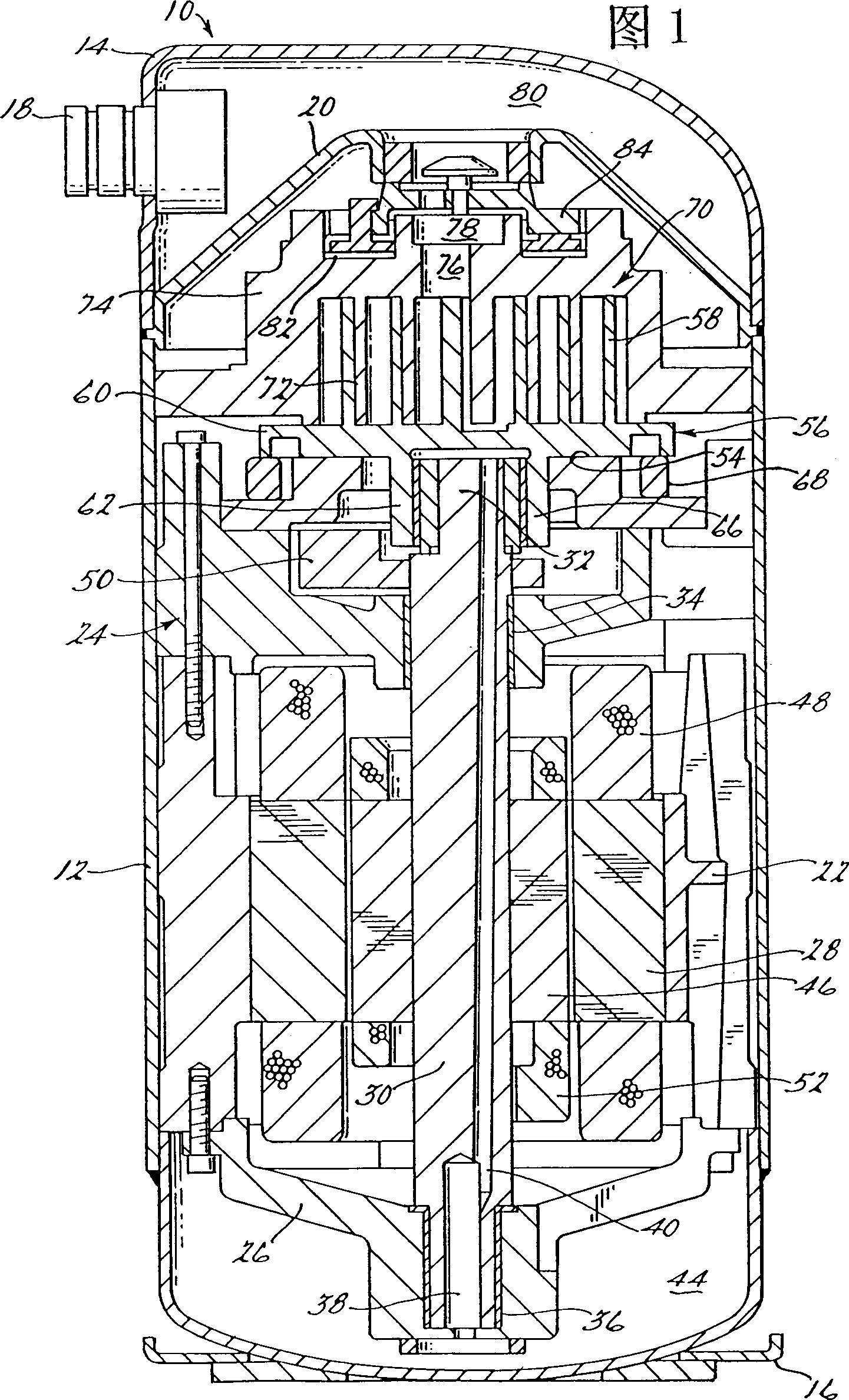
[0019] Referring now to the drawings, in which like numerals indicate like or corresponding parts throughout the several views, there is shown in FIGS. 1 and 2 a screw compressor including the unique The Oldham coupling, and generally indicated by the number 10. Screw compressor 10 includes a generally cylindrical hermetic casing 12 having a cover 14 welded at its upper end and a base 16 welded at its lower end having several Formed mounting feet (not shown). The cover 14 is equipped with a refrigerant discharge connection 18 which may have a customary discharge valve therein. A transversely extending bulkhead 20 is secured to the housing 12 by welding around the perimeter of the housing 12 at the same points as the cover 14 is welded to the housing 12, and a compressor mounting frame 22 is press fit inside the housing 12 and Supported by the end of the base 16 . The diameter of the base 16 is slightly smaller than the diameter of the housing 12 so that the base 16 is seate...


PUM


Abstract

A screw compressor has a pair of intersecting screws. An Oldham coupling is secured to the orbiting helix to prevent the orbiting helix from rotating. This Oldham coupling has keys which slide in grooves. One of the sides of each key is the loading side and the opposite side is the non-loading side. The non-loading side of the key has a step or profile to provide clearance for key deflection. In another embodiment, the step or profile is provided on the non-loading side of the trough.

Description

technical field [0001] This invention relates to screw machines. More specifically, the present invention relates to a screw machine having a gap between the screw and the Oldham coupling that allows the key of the Oldham coupling to deflect. Background technique [0002] Within the art commonly referred to as screw machines, there is a class of machines used for the movement of various types of fluids. The screw machine can be shaped as an expander, displacement engine, pump, compressor, etc., and the features of the present invention are applicable to any of these machines. However, for purposes of illustration, the disclosed embodiments are in the form of hermetic refrigerant screw compressors. [0003] Screw compressors have become increasingly popular as compressors in both refrigeration and air conditioning applications, primarily due to their extremely efficient operating capabilities. Typically, these machines comprise a pair of intermeshing helical belts, one of ...

Claims


Application Information

Patent Timeline
IPC IPC(8): F04C18/02F01C17/06F16D3/70
CPCF01C17/066F16D3/70F04C18/02F16D3/04
Inventor 哈里·克伦登因
Owner EMERSON CLIMATE TECH INC
Why Eureka
Try Eureka