Check patentability & draft patents in minutes with Patsnap Eureka AI!

System and method of controlling power consumption in a digital phase locked loop (DPLL)

A phase-locked loop and control signal technology, applied in the field of phase-locked loops, can solve the problem of spending a lot of time

Active Publication Date: 2011-04-13
QUALCOMM INC
View PDF6 Cites 3 Cited by
  • Summary
  • Abstract
  • Description
  • Claims
  • Application Information

AI Technical Summary

Problems solved by technology

However, these methods typically take a significant amount of time to perform frequency change and relock operations, which may not be acceptable in many applications

Method used


Image

  • System and method of controlling power consumption in a digital phase locked loop (DPLL)
  • System and method of controlling power consumption in a digital phase locked loop (DPLL)
  • System and method of controlling power consumption in a digital phase locked loop (DPLL)

Examples


Embodiment Construction

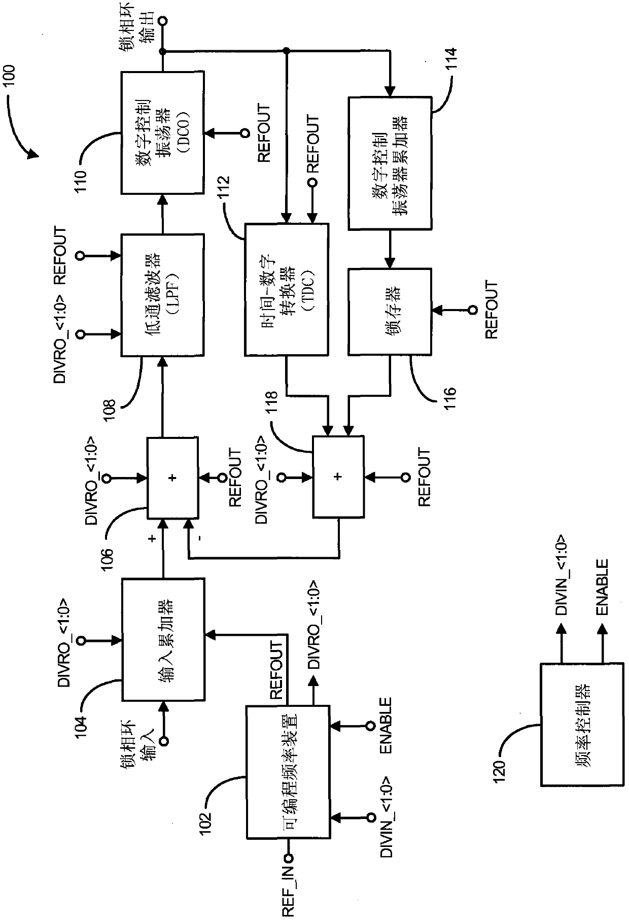
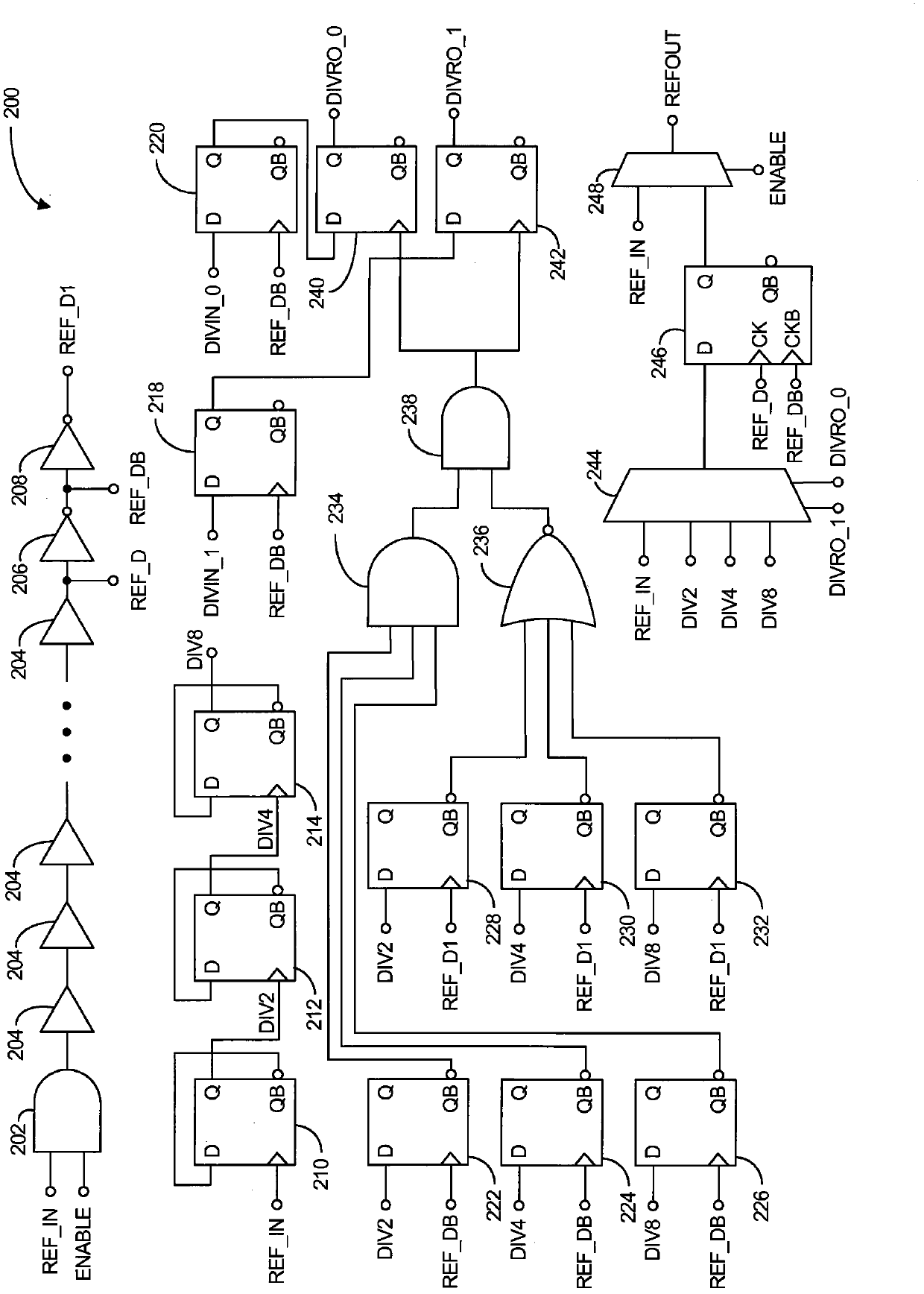
[0014] figure 1 A block diagram of an exemplary digital phase locked loop (DPLL) 100 is illustrated in accordance with an aspect of the invention. In summary, the DPLL allows programmability of the frequency of the reference clock for power consumption purposes without significantly affecting the loop control of the DPLL. The DPLL performs this process by ensuring that the timing of the reference clock's trigger edge does not substantially change when the reference clock frequency changes. As previously discussed, the DPLL can be placed in a low power mode when the frequency of the reference clock is substantially reduced. Conversely, the DPLL can be placed in a high power mode when the frequency of the reference clock is substantially increased.

[0015] Specifically, a DPLL includes a programmable frequency device 102, an input accumulator 104, a first summing device 106, a low-pass filter (LPF) or loop filter 108, a digitally controlled oscillator (DCO) 110, a time-to-dig...


PUM


Abstract

An apparatus comprising a programmable frequency device adapted to generate a reference clock selected from a set of distinct frequency clocks, wherein the programmable frequency device is further adapted to maintain the same temporal relationship of the triggering edges of the reference clock when switching between the distinct frequency clocks. The apparatus further comprises a phase locked loop (PLL), such as a digital PLL (DPLL), that uses the selected reference clock to establish a predetermined phase relationship between an input signal and an output signal. By maintaining substantially the same temporal relationship of the reference clock when switching between distinct frequency clocks, the continual and effective operation of the phase locked loop (PLL) is not significantly disturbed while changing the reference clock. This may be used to control the power consumption of the apparatus.

Description

technical field [0001] The present invention relates generally to phase locked loops (PLLs), and in particular to a system and method of controlling power consumption in a digital phase locked loop (DPLL). Background technique [0002] Communication devices typically include a local oscillator (LO) for synchronously transmitting signals to and receiving signals from other remote communication devices. Typically, these signals are sent or received via defined frequency channels. To select a particular frequency channel, the frequency of the LO is typically changed so that signals are properly transmitted or received via the selected channel. Typically, a phase locked loop (PLL), such as a digital phase locked loop (DPLL), is used to perform the change of the LO frequency. [0003] A typical DPLL includes several digital devices such as an input accumulator, a low-pass filter (LPF) (often referred to as a "loop filter"), a digitally controlled oscillator (DCO), a DCO accumul...

Claims


Application Information

Patent Timeline
IPC IPC(8): H03L7/00H03L7/08
CPCH03L7/00H03L2207/50H03L7/0802H03L7/183
Inventor 孙博加里·约翰·巴兰坦居坎瓦尔·辛格·萨霍塔
Owner QUALCOMM INC
Features
  • R&D
  • Intellectual Property
  • Life Sciences
  • Materials
  • Tech Scout
  • Unparalleled Data Quality
  • Higher Quality Content
  • 60% Fewer Hallucinations
Learn More