
Hip joint extension orthosis

An orthosis and hip joint technology, applied in the field of medical devices, can solve the problems of children's eczema, pressure ulcers, increased incidence of ischemic femoral head necrosis in children, cumbersome and other problems, and achieve no complications, novel structure and convenient use. Effect

Inactive Publication Date: 2011-04-20
曹志洪
View PDF0 Cites 1 Cited by
  • Summary
  • Abstract
  • Description
  • Claims
  • Application Information

AI Technical Summary

Problems solved by technology

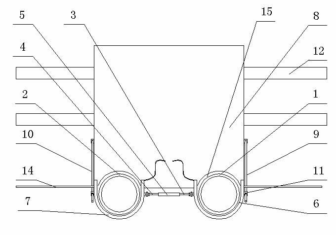
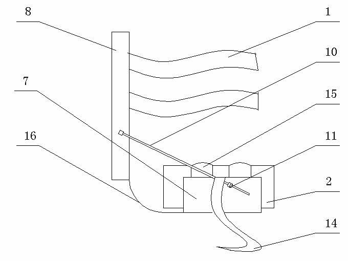
[0002] At present, for children with developmental dislocation of the hip, the osteopaths in the hospital treat them with hip abduction and external fixation brackets, which include the left fixation sleeve , the right fixed sleeve, the positioning rod and the adjusting bolt. The two ends of the positioning rod are respectively hinged with the left and right fixed sleeves through the adjusting bolts to adjust the abduction angle of the hip joint. The fixed sleeve is composed of an upper hoop and a lower hoop One side of the upper hoop and the lower hoop are flexibly connected by a hinge, and the other side is connected by Velcro. The inner side and both ends of the upper hoop and the lower hoop are covered by padding to make the patient more comfortable to use , its shortcoming is: the maximum hip abduction can only reach 90°, external rotation, and flexion can reach 90°, and then add gypsum to adjust and fix. This fixation takes 4-6 months. Because the gypsum is airtight and heavy, it is easy to cause harm to children. Eczema, pressure sores, and severe cases increase the incidence of ischemic femoral head necrosis in children

Method used


Image

  • Hip joint extension orthosis
  • Hip joint extension orthosis
  • Hip joint extension orthosis

Examples


Embodiment Construction

[0012] Below in conjunction with accompanying drawing, the present invention is further described:

[0013] A hip joint abduction orthosis comprises a left fixed sleeve 1, a right fixed sleeve 2, a left positioning rod 3 and a right positioning rod 4, the fixed sleeves 1 and 2 are composed of an upper hoop and a lower hoop, and the upper hoop and the One side of the lower ferrule is movably connected by a hinge, and the other side is connected by Velcro. The inner side and both ends of the upper ferrule and the lower ferrule are covered by pads. It is characterized in that there are tension nuts 5, left The adjustment seat 6, the right adjustment seat 7 and the tie belt 14, the two ends of the inner hole of the tension nut 5 are provided with reverse threaded holes, one end of the tension nut 5 is connected with the left adjustment seat 6 through the left positioning rod 3, and the other end Connect the right positioning rod 4 with the right adjustment seat 7, rotate the tensi...


PUM


Abstract

The invention relates to the technical field of medical equipment, in particular to a hip joint extension orthosis. The hip joint extension orthosis comprises a left fixing sleeve, a right fixing sleeve, a left locating rod and a right locating rod, and is characterized in that a tensioning nut, a left adjusting base, a right adjusting base and bound bands are arranged, reverse screwed holes are arranged at two ends of the inner hole of the tensioning nut, one end of the tensioning nut is connected with the left adjusting base by the left locating rod, and the other end of the tensioning nut is connected with the right adjusting base through the right locating rod, the adjusting bases are U-shaped and are respectively sheathed outside the left fixing sleeve and the right fixing sleeve, the bound bands are arranged on the outer walls of the adjusting bases, ring-shaped grooves are arranged on the inner walls of the adjusting bases, the left fixing sleeve and the right fixing sleeve are respectively matched with arc-shaped grooves on the inner wall of the adjusting bases through convex rings arranged outside the left fixing sleeve and the right fixing sleeve, screw holes are arranged on the adjusting bases, and the adjusting bases are respectively connected with the left fixing sleeve and the right fixing sleeve by top threads. The hip joint extension orthosis has the advantages that the structure is novel; the usage is convenient; operation, pain and complications are not caused; and the recovery is fast.

Description

technical field [0001] The invention relates to the technical field of medical appliances, in particular to a hip joint abduction orthosis. Background technique [0002] At present, for children suffering from developmental dislocation of the hip, the osteopaths in the hospital treat them with hip abduction and external fixation brackets, which include left fixation sleeves, right fixation sleeves, positioning rods and adjustment bolts. The adjustment bolts are respectively hinged with the left and right fixed sleeves to adjust the abduction angle of the hip joint. The fixed sleeve is composed of an upper hoop and a lower hoop, and one side of the upper hoop and the lower hoop are movable through the hinge The other side is connected by Velcro, and the inside and both ends of the upper and lower hoops are covered by padding, which makes it more comfortable for patients to use. The disadvantage is that the maximum hip abduction can only reach 90° , external rotation, and fl...

Claims


Application Information

Patent Timeline
Patent Type & Authority Applications(China)
IPC IPC(8): A61F5/05
Inventor 曹志洪程宁宋艳芹
Owner 曹志洪
Learn More