Method and device for laying unidirectional fiber layer on mobile bracket and method for producing multi axial cloth

A unidirectional fiber, multi-axial technology, applied in the direction of non-woven fabrics, textiles and papermaking, flat warp knitting machines, etc., can solve the decisive obstacle of the storage unit assembly time and other problems

Active Publication Date: 2015-02-25
KARL MAYER TECH TEXTILIEN GMBH
View PDF7 Cites 0 Cited by
  • Summary
  • Abstract
  • Description
  • Claims
  • Application Information

AI Technical Summary

Problems solved by technology

[0013] The unavoidable set-up time of the last stock unit is a decisive obstacle when striving for higher production speeds

Method used


Image

  • Method and device for laying unidirectional fiber layer on mobile bracket and method for producing multi axial cloth
  • Method and device for laying unidirectional fiber layer on mobile bracket and method for producing multi axial cloth
  • Method and device for laying unidirectional fiber layer on mobile bracket and method for producing multi axial cloth

Examples


Embodiment Construction

[0036] figure 1 A top view of a first embodiment of the invention is shown. figure 1 And the following figures are only schematic diagrams, which should show important parts. according to figure 1 Place the unidirectional fiber layer onto support 1. Carriage 1 moves in direction 2 , ie in the illustration from top to bottom. The carrier 1 can generally be formed by two conveyor chains 3 , between which the individual sections 18 are clamped in clamping devices (not shown) and thus also supported. The next processing station is indicated with reference number 4 . For example, the reference numeral 4 may designate a bobbin on which the finished unidirectional fiber layer is wound in this respect. However, the reference numeral 4 can also designate the next section supply station, in which, for example, a next unidirectional fiber layer is laid on an already existing fiber layer. if in figure 1 The unidirectional fiber layer shown in is the uppermost and last fiber layer w...


PUM


Abstract

#CMT# # / CMT# The method for applying a band-, strip-, or web-shaped unidirectional fiber layer formed from individual segment (18) on a self-moving support (1), whose movement direction corresponds to longitudinal direction of the emerging fiber layer, comprises obtaining a fiber band from a supply unit, guiding transverse to the movement direction of the support and then transferring by a laying device (12a, 12b) at the moving support. The supply unit and the laying device form two segment-feed stations (5a, 5b) that are arranged in the movement direction of the support. #CMT# : # / CMT# The method for applying a band-, strip-, or web-shaped unidirectional fiber layer formed from individual segment (18) on a self-moving support (1), whose movement direction corresponds to longitudinal direction of the emerging fiber layer, comprises obtaining a fiber band from a supply unit, guiding transverse to the movement direction of the support and then transferring by a laying device (12a, 12b) at the moving support. The supply unit and the laying device form two segment-feed stations (5a, 5b) that are arranged in the movement direction of the support and provide the segments to the unidirectional fiber layer. A gripper (10a, 10b) removes the front section of the fiber layer that is held in coil form, by the supply unit, and guides over the support. The segment is formed through the separation of the front section by the fiber layer and the gripper is a component of each segment-feed station. The movement direction in which the front section of the fiber layer is guided by the supply unit to the support is opposed in adjoining segment-feed station. The segments are transferred to space in the two segment-feed stations, where the space produced in one of the feed stations is filled in another feed station. The two segment-feed stations are simultaneous or alternate in operation. The process time of the segment-feed stations collapses with the setup time of another segment-feed station. The operation of the segment and the space are determined in ongoing operation. The adjustment of the segment and the space is carried out after the standard of the determined values through changing the operation speed of the laying arrangement and the operation of the segment in such a way that the segment feed-stations connect to each other in overlap-free manner. Each segment-feed station is operated with two supply units that exist itself on opposite sides of the moving support. The laying device present between both supply units is loaded by the supply unit. The gripper removes the fiber layer from the supply units of each segment-feed station in changing operation. The segment-feed stations are started to each other and the four supply units are shifted in the set-up time in such a way that an optimization of the production speed is obtained. The segment-feed stations are operated in changing operation with only interchangeable supply units that are guidable and are coupled at one of both segment-feed stations. The unidirectional fiber layer is applied by individual segment-feed station that is operated with a first and second supply unit that present itself on opposite sides of the moving support. Independent claims are included for: (1) a method for the production of band-, strip-, or web-shaped multiaxial layers; (2) an arrangement for applying a band-, strip-, or web-shaped unidirectional fiber layer formed from individual segment on a self-moving support; and (3) a multiaxial machine for the production of band-, strip-, or web-shaped multiaxial layers. #CMT#USE : # / CMT# The method for applying a band-, strip-, or web-shaped unidirectional fiber layer formed from individual segment on a self-moving support useful for the production of band-, strip-, or web-shaped multiaxial layers. #CMT#
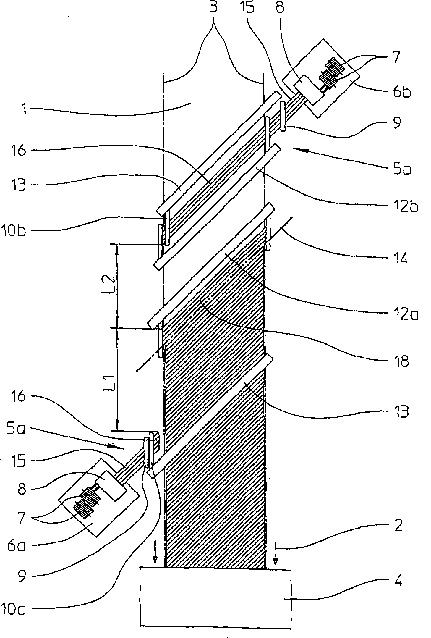
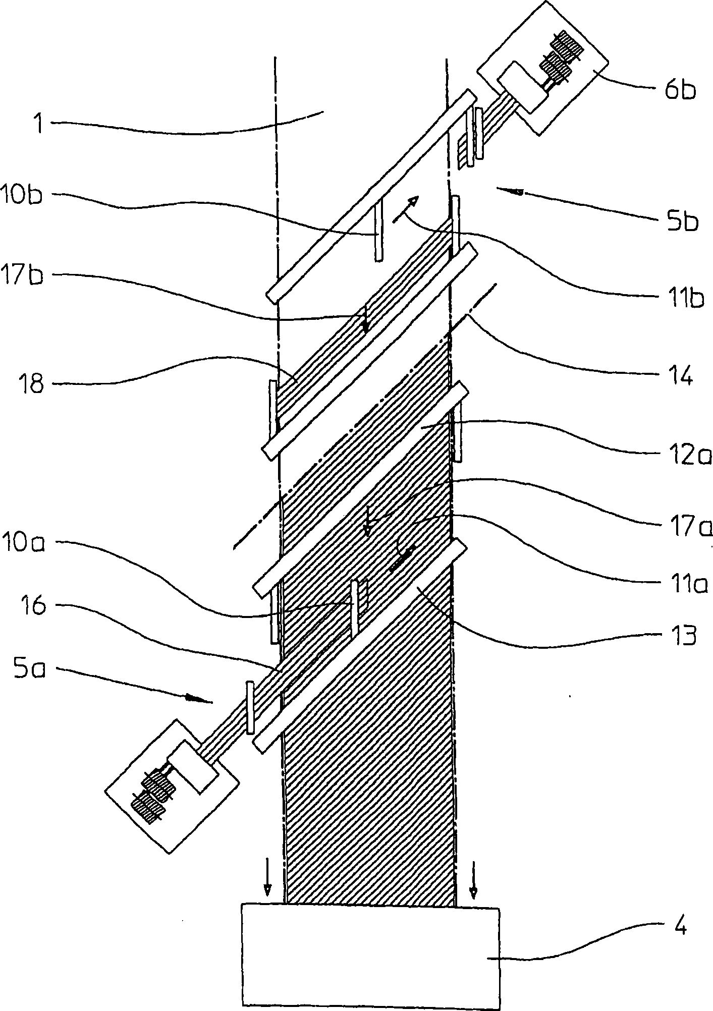
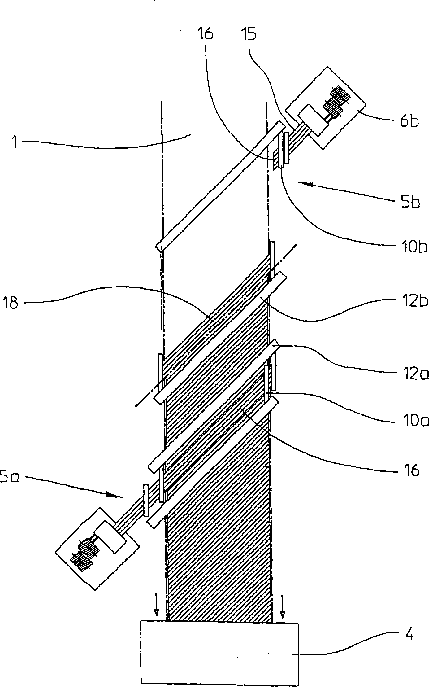
ADVANTAGE : # / CMT# The method ensures simple and efficient application of a band-, strip-, or web-shaped unidirectional fiber layer formed from individual segment on a self-moving support with good quality. #CMT#DESCRIPTION OF DRAWINGS : # / CMT# The figure shows a schematic representation of an arrangement for applying a band-, strip-, or web-shaped unidirectional fiber layer formed from individual segment on a self-moving support. 1 : Support 5a, 5b : Segment-feed station 10a, 10b : Gripper 12a, 12b : Laying device 18 : Segment.

Description

technical field [0001] Method and device for laying unidirectional fiber layers as well as method and multiaxial weaving machine for producing multiaxial cloth. [0002] The invention relates to a method for applying a strip-shaped, strip-shaped or web-shaped unidirectional fiber layer consisting of individual segments to a mobile support according to the preambles of claims 1, 13 and 16. Background technique [0003] Such methods and devices belong to the prior art, eg from EP2003232A1. The unidirectional fiber layers described in the present invention are generally used to make multi-axial cloths, wherein a certain number of unidirectional fiber layers are stacked segment by segment with different fiber directions. A carrier in the sense of the present invention is an endless conveying device for the initially deposited fibrous layer which is moved in the longitudinal direction of the formed fibrous layer and thus of the subsequently formed multiaxial cloth. The conveyin...

Claims


Application Information

Patent Timeline
Patent Type & Authority Patents(China)
IPC IPC(8): D04B23/10D04B27/10D04H1/74
CPCD04H1/74D04H3/04B29C70/20B29C70/50B29C2793/0072B29C2793/0081
Inventor 莱纳·索依斯罗兰德·施密特
Owner KARL MAYER TECH TEXTILIEN GMBH
Why Eureka
Try Eureka