
Wire arrangement body, busbar module and power-supply unit

A busbar and wiring technology, applied in the field of wiring body, can solve the problem of not protecting multiple wires 105

Active Publication Date: 2011-04-20
YAZAKI CORP
View PDF4 Cites 38 Cited by
  • Summary
  • Abstract
  • Description
  • Claims
  • Application Information

AI Technical Summary

Problems solved by technology

However, the bent first hinge 191 returns to the original shape (in other words, the lid portion 167 is opened), and there occurs a tendency to rotate the lid portion 167 in the width direction from the center position P of the first hinge 191 counterclockwise in the drawing. The rotational force F1 (in other words, the force to turn the lid portion 167 upward about the first hinge 191 as the center of rotation), so there is the other side edge portion ( edge portion of the other side wall portion) floating concerns, and the cover portion 167 is opened
Thus, since the cover portion 167 as Figure 9B As shown, it is opened, so that the electric wire 105 is stuck between the second receiving portion 164 and the cover portion 167 (or the snapping of the electric wire), or the electric wire 105 is as Figure 9C Shown is disengaged from the second receiving portion 164, so there is a problem of not protecting the plurality of wires 105

Method used


Image

  • Wire arrangement body, busbar module and power-supply unit
  • Wire arrangement body, busbar module and power-supply unit
  • Wire arrangement body, busbar module and power-supply unit

Examples


Embodiment Construction

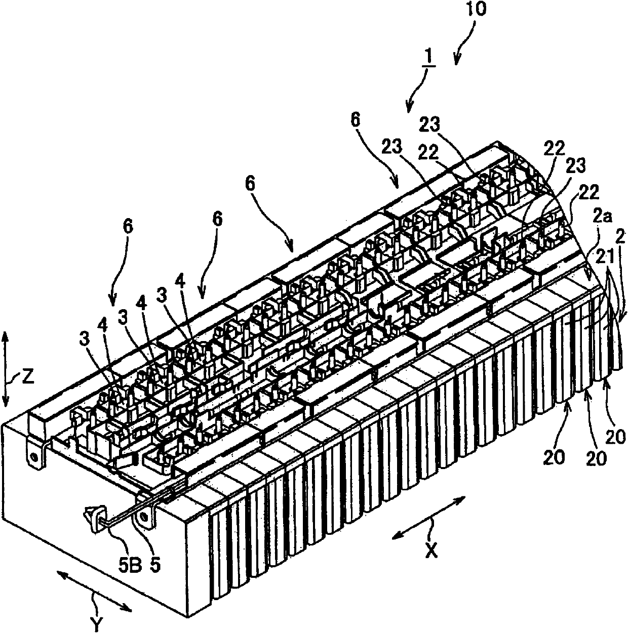
[0028] refer to Figure 1 to Figure 6 Embodiments of the power supply apparatus according to the present invention are described. Also, for the convenience of description, an arrow X, an arrow Y, and an arrow Z are used to indicate the arrangement direction of each member in each drawing. Arrow X, arrow Y, and arrow Z are orthogonal to each other.

[0029] figure 1The power supply device 10 includes a battery assembly 2 and a bus bar module 1 stacked and connected to the battery assembly 2 . The power supply apparatus 10 is mounted on an electric vehicle that runs with a battery motor or a hybrid vehicle that runs with an engine and an electric motor together and supplies electric power to the electric motor.

[0030] The storage battery assembly 2 consists of one direction ( figure 1 Arrow X direction in ) is configured by a plurality of storage batteries 20 arranged in a row and fixed to each other. Each battery 20 includes a battery body 21 in the shape of a rectangu...


PUM


Abstract

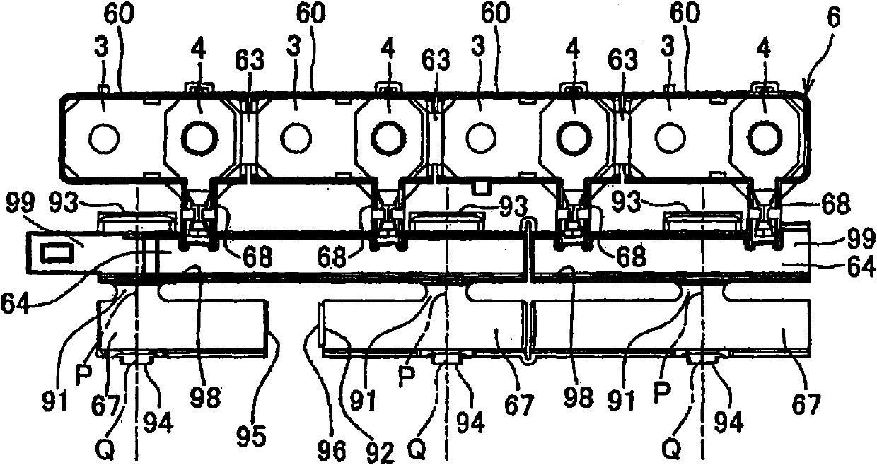
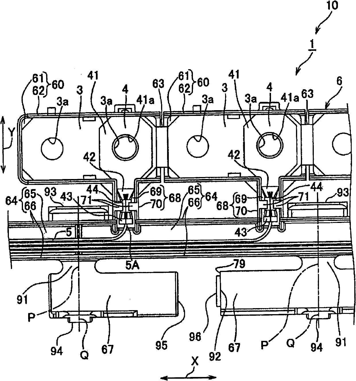
A wire arrangement body includes: a wire arrangement groove portion of a tank shape that has a bottom wall portion and both side wall portions; a lid portion that is rotatably connected to one side wall portion of the wire arrangement groove portion through a hinge and covers the wire arrangement groove portion so as to seal a groove opening of the wire arrangement groove portion; and an engagement portion that causes the lid portion to engage with the other side wall portion of the wire arrangement groove portion when the lid portion covers the wire arrangement groove portion. The wire arrangement body is provided so that a center position of the hinge and a center position of the engagement portion are aligned in parallel with a width direction of the wire arrangement body.

Description

technical field [0001] The present invention relates to a power supply device used in hybrid vehicles, electric vehicles, etc., a bus bar module constituting the power supply device, and a wiring body constituting the bus bar module. Background technique [0002] For example, a power feeding apparatus shown in JP-A-2009-43637 (WO 2009 / 022521A1) is installed in various vehicles such as an electric vehicle running with an electric motor, a hybrid vehicle running with both an engine and a motor, as a power source for the motor. The power supply equipment includes: a storage battery assembly having a plurality of storage batteries, in which a positive electrode is provided on one end and a negative electrode is provided on the other end, and the positive electrodes and the negative electrodes are alternately arranged adjacent to each other; and a bus bar module, the bus bar module Overlaid on the surface of the battery assembly on which the electrodes are provided. [0003] F...

Claims


Application Information

Patent Timeline
IPC IPC(8): H01M2/20H01M50/503H01M50/507H01M50/51H01M50/517H01M50/522
CPCH01M2/206Y02E60/12H01M2/22Y02E60/10H01M50/528H01M50/51H01M50/507H01M50/517H01M50/503H01M50/522
Inventor 小笠原茂之青木敬三
Owner YAZAKI CORP
Learn More