
Signal detection method, detection device and detection base station

A signal detection and signal technology, applied in the field of communication, to achieve the effects of reducing influence, reducing uncertain errors, and improving standing wave detection accuracy

Active Publication Date: 2013-06-26
HUAWEI TECH CO LTD
View PDF8 Cites 0 Cited by
  • Summary
  • Abstract
  • Description
  • Claims
  • Application Information

AI Technical Summary

Problems solved by technology

[0004] The invention provides a signal detection method, a signal detection device and a base station to reduce the uncertain error caused by the unsatisfactory directionality of the coupler

Method used


Image

  • Signal detection method, detection device and detection base station
  • Signal detection method, detection device and detection base station
  • Signal detection method, detection device and detection base station

Examples


Embodiment Construction

[0026] Embodiments of the present invention provide a signal detection method, a signal detection device, and a base station to reduce the uncertain error caused by the unsatisfactory directivity of the coupler, so that the influence of the directivity of the coupler on the characteristic parameters of impedance matching can be corrected, and the The influence of the directionality of the coupler on the standing wave detection accuracy, and improve the standing wave detection accuracy.

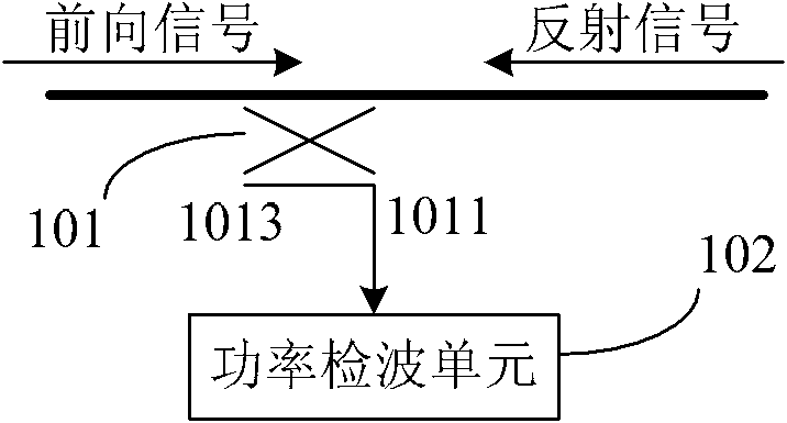
[0027] In the prior art, usually such as figure 1 A single directional coupler 101 is shown, the directional coupler can couple the input signal and output the coupled signal from the coupled end. Taking a directional coupler coupling a signal on a radio frequency channel as an example, the directional coupler 101 can couple a forward signal or a reflected signal on the radio frequency channel, that is, the input signal is a forward signal or a reflected signal on the radio frequency channel. ...


PUM


Abstract

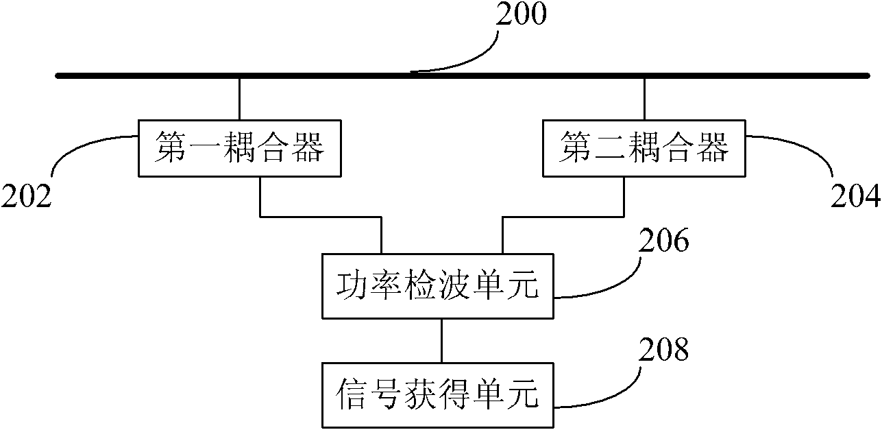
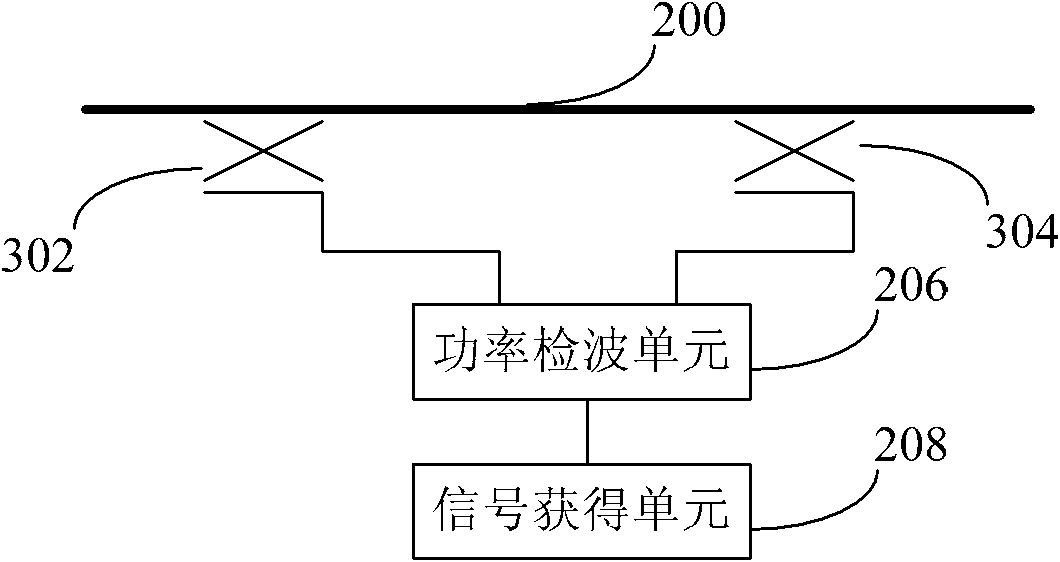
The invention provides a signal detection method of signal, a detection device and a detection base station. The signal detection device comprises a first coupler, a second coupler, a power detection unit and a signal acquiring unit. The length of the transmission line between the first coupler and the second coupler is odd times as long as quarter wave, and the first coupler and the second coupler have the same directivity. The power detection unit is connected with the first coupler and the second coupler to perform the power detection on the signals output by the first coupler and the second coupler, thus respectively obtaining a first detection result and a second detection result of the signal power on the channel to be detected. The signal acquiring unit is connected with the power detection unit to obtain the average value of the first detection result and the second detection result, and the average value is used as a third detection result of the signal power on the channel to be detected. By using the method, the device and the base station provided by the invention, the uncertain errors caused by the unsatisfactory directivity of the coupler can be reduced.

Description

technical field [0001] The invention relates to the field of communication technology, in particular to a signal detection method, a signal detection device and a base station. Background technique [0002] In a wireless communication system, standing wave ratio detection is an important means to measure the working status of the signaling system. At present, the commonly used method for VSWR detection is to use a directional coupler to couple the signal on the radio frequency channel, which includes a forward signal and a reflected signal, and then use the power of the coupled forward signal and the power of the coupled reflected signal to Calculate standing wave ratio, reflection coefficient and other characterization quantities that reflect the matching degree between the characteristic impedance of the feeder and the load impedance (abbreviated as impedance matching characterization parameters). [0003] During the research process of the present invention, the inventor...

Claims


Application Information

Patent Timeline
Patent Type & Authority Patents(China)
IPC IPC(8): H04B17/00H04W24/08H04B17/318
Inventor 曾志雄孙益军孙捷
Owner HUAWEI TECH CO LTD
Learn More