Claw chuck inner displacement structure for toe lasting machine

A technology of front upper machine and front claw plate, which is applied in the direction of shoe uppers, clothing, footwear, etc., can solve the problem that the edge of the upper can not be completely attached to the edge of the last, so as to improve the operation rate and operability, and the upper Smooth, maintenance-friendly effect

Active Publication Date: 2013-07-24
DONGGUAN QIFENG HYDRAULIC TECH
View PDF6 Cites 0 Cited by
  • Summary
  • Abstract
  • Description
  • Claims
  • Application Information

AI Technical Summary

Problems solved by technology

[0004] The purpose of the present invention is to provide a claw plate internal movement structure of the front upper machine, which can realize the action of pulling down and retracting the edge of the shoe upper to close to the edge of the last, and overcoming the inability of the traditional upper shoe to reach the edge of the shoe upper completely. Defects on last edge

Method used


Image

  • Claw chuck inner displacement structure for toe lasting machine
  • Claw chuck inner displacement structure for toe lasting machine

Examples


Embodiment Construction

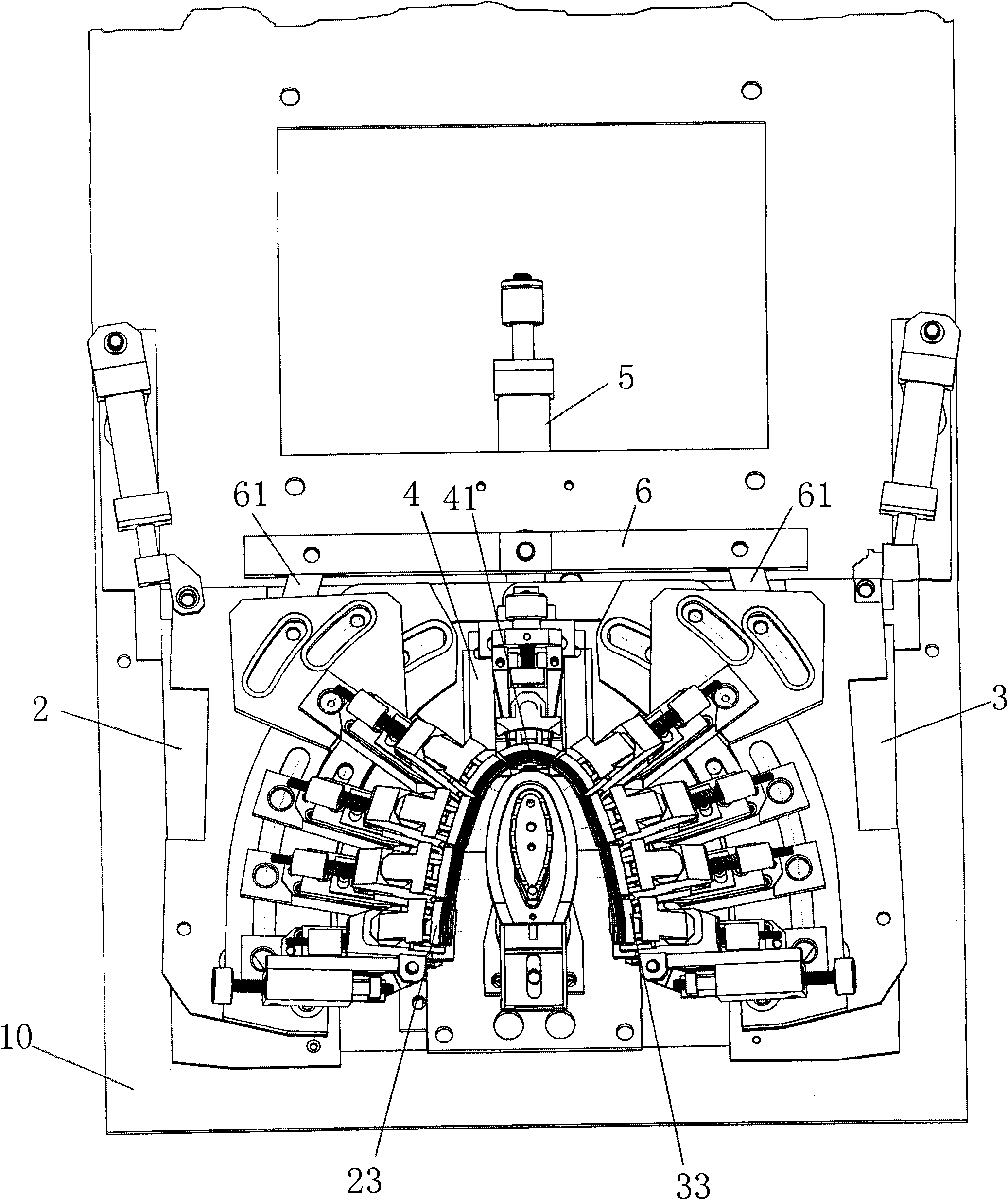
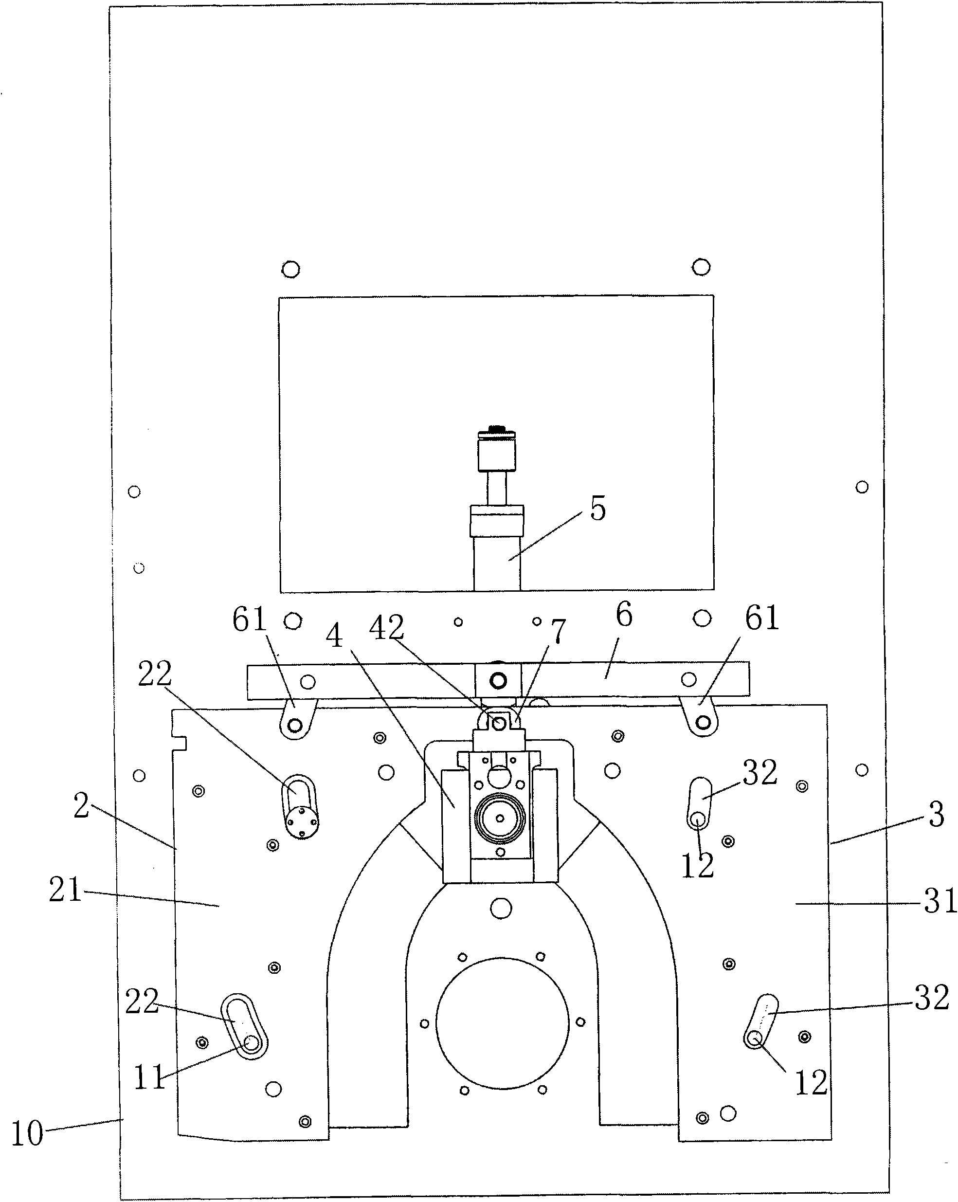
[0018] refer to figure 1 , 2 As shown, it is a structural schematic diagram of the present invention, and the structure of the claw plate moving inward of the front lasting machine according to the present invention includes:

[0019] A left claw plate 2 is movably installed on the large plate 10 of the machine. The left claw plate 2 has an upward first mounting surface 21 and a first moving guide groove 22. The first moving guide groove 22 cooperates with the first moving guide groove on the large plate. A restricting part 11 is installed, and a number of left claws 23 are installed on the first installation surface 21 . The first moving guide groove 22 is a waist-shaped arc groove, and the first restricting part 11 is a convex pin fixed on a large plate. When the left claw plate 2 moves, the first restricting part 11 gives guidance and positioning, so that the left claw plate 2 moves according to the arc direction of the first moving guide groove 22, and ensures that the l...


PUM


Abstract

The invention relates to the technical field of shoemaking machinery, in particular to a toe lasting machine. The toe lasting machine comprises a left claw chuck, a right claw chuck and a front claw chuck which are movably arranged on a large plate of the machine; the left claw chuck is provided with a first mounting surface and a first moving guide slot, which face upwards; the first moving guide slot is arranged to be matched with a first limiting part on the large plate; a plurality of left claws are arranged on the first mounting surface; the right claw chuck is symmetrical to the left claw chuck and is provided with a second mounting surface and a second moving guide slot, which face upwards; the second moving guide slot is arranged to be matched with a second limiting part on the large plate; a plurality of right claws are arranged on the second mounting surface; front claws are arranged on the front claw chuck, and the front claws, the left claws and the right claws are arranged and distributed on the periphery of a shoe last holding station respectively; and a power cylinder synchronously drives the left claw chuck and the right claw chuck through a push rod, while the left claw chuck and the right claw chuck are combined to drive the front claw chuck. Due to cooperative inner displacement of the left claw chuck, the right claw chuck and the front claw chuck, the vamp edge is completely attached to the shoe last, and the lasted vamp is smooth and flat and has no wrinkle or hollowing.

Description

Technical field: [0001] The invention relates to the technical field of shoemaking machinery, in particular to a front upper machine. Background technique: [0002] The front upper machine is a commonly used production machine in the automatic production of shoes, mainly used for upper upper processing. When working, the claws on the machine grasp the edge of the shoe upper, the last pushes up on the underside of the shoe upper, and the edge of the shoe upper is relatively pulled down, so that the shoe upper is tightly covered on the surface of the shoe last, and then through the machine on the The pressing device presses the upper on the last, and the edge of the upper is folded inward and attached to the lower side of the last, and then used for gluing processing. In the traditional front upper machine, the claws grab the edge of the upper and only do a single relatively vertical pull-down action, while the edge of the last is inward and curved, so that in actual producti...

Claims


Application Information

Patent Timeline
Patent Type & Authority Patents(China)
IPC IPC(8): A43D11/10
Inventor 李国阳
Owner DONGGUAN QIFENG HYDRAULIC TECH
Why Eureka
Try Eureka