
Diagrid sleeve structure for restricting connection of high strength concrete nodes

A high-strength concrete and node connection technology, applied in the direction of building structure, construction, etc., can solve the problems of difficulty in meeting the basic requirements of strong nodes and weak components, low bearing capacity of reinforced concrete nodes, and difficulty in making and supporting formwork, so as to improve the ductility of nodes. , The effect of simplifying the production of joints and supporting the formwork, and simplifying the construction procedures of the structure

Inactive Publication Date: 2011-04-27
HARBIN INST OF TECH
View PDF4 Cites 7 Cited by
  • Summary
  • Abstract
  • Description
  • Claims
  • Application Information

AI Technical Summary

Problems solved by technology

[0003] The purpose of the present invention is to solve the problem that the existing oblique grid tube structure reinforced concrete joints have low bearing capacity and high brittleness, and it is difficult to meet the basic requirements of strong joints and weak members, and it is difficult to make and support the formwork, and it is difficult to ensure the construction quality and high cost technical problems, and then provides a diagonal grid tube structure connected by constrained high-strength concrete nodes

Method used


Image

  • Diagrid sleeve structure for restricting connection of high strength concrete nodes
  • Diagrid sleeve structure for restricting connection of high strength concrete nodes
  • Diagrid sleeve structure for restricting connection of high strength concrete nodes

Examples


specific Embodiment approach 1

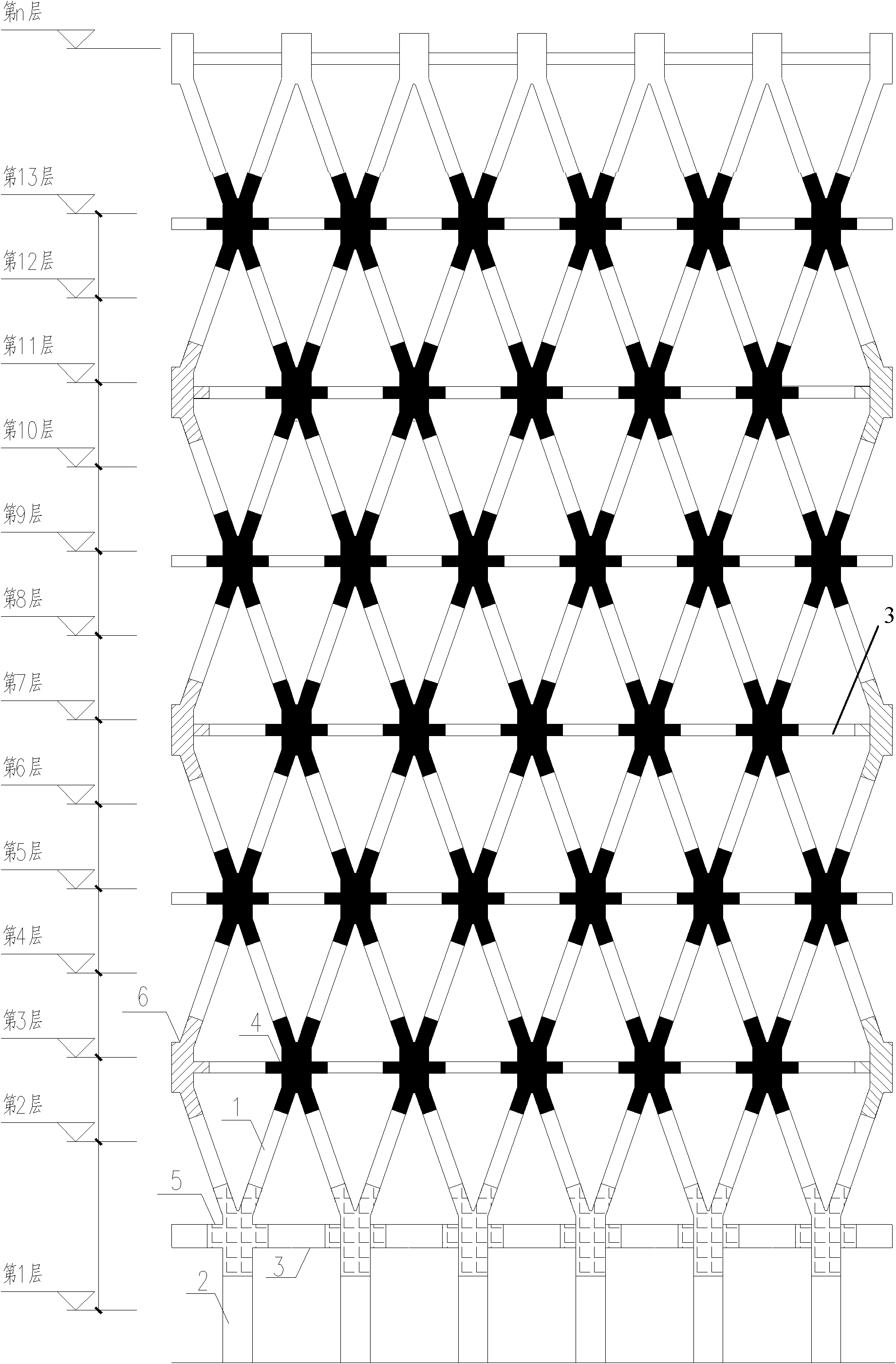
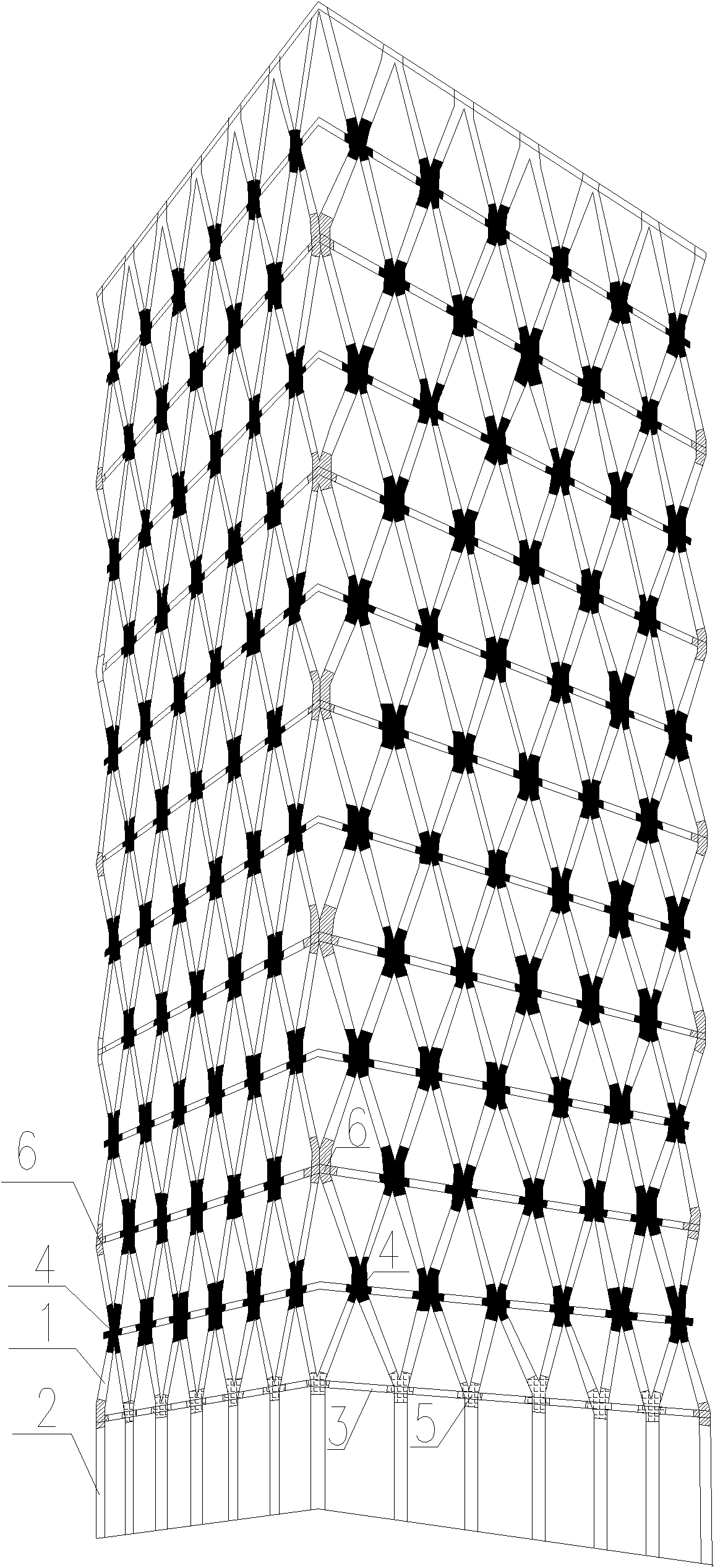
[0009] Specific implementation mode one: as Figure 1~5 As shown, the oblique grid tube structure connected by constrained high-strength concrete nodes in this embodiment includes a plurality of reinforced concrete cross slanted columns 1, a plurality of reinforced concrete columns 2, a plurality of reinforced concrete girders 3, and a plurality of A constrained high-strength concrete facade intersection node 4, multiple constrained high-strength concrete slanted column conversion nodes 5, and multiple constrained high-strength concrete space intersection nodes 6; multiple reinforced concrete columns 2 are all arranged on the ground floor, and each reinforced concrete column The upper end of 2 is connected to the lower ends of two reinforced concrete cross slanted columns 1 through a constrained high-strength concrete slanted column conversion node 5, and every two constrained high-strength concrete slanted column conversion nodes 5 are connected through a reinforced concrete g...

specific Embodiment approach 2

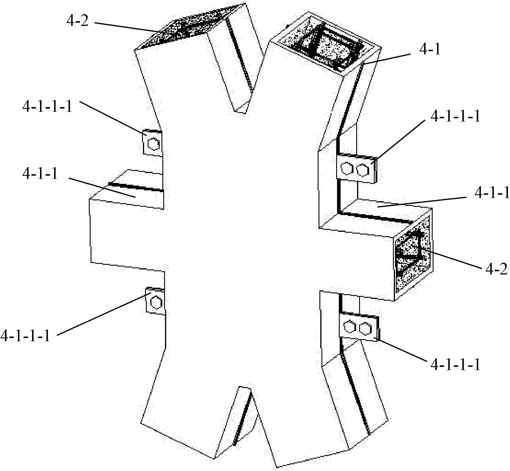
[0011] Specific implementation mode two: as Figure 1~5 As shown, each constrained high-strength concrete façade intersection node 4 in this embodiment is composed of an external intersection node steel formwork 4-1 and an intersection node reinforced high-strength concrete 4-2 built in its cavity. Other components and connections are the same as those in the first embodiment.

specific Embodiment approach 3

[0012] Specific implementation mode three: as Figure 1~5 As shown, each constrained high-strength concrete slanted column transfer node 5 in this embodiment is composed of an external transfer node steel formwork 5-1 and a transfer node reinforced high-strength concrete 5-2 built in its cavity. Other compositions and connections are the same as those in Embodiment 1 or 2.


PUM


Abstract

The invention provides a diagrid sleeve structure for restricting connection of high strength concrete nodes, relates to a diagrid sleeve structure in the field of civil engineering, and aims to solve the problems that the conventional reinforced concrete node with the diagrid sleeve structure has lower bearing capacity and high brittleness, is difficult to meet the basic requirements of strong nodes and weak components, and the like. In the structure, the upper end of each reinforced concrete column is connected with lower ends of two reinforced concrete counter braces through a high-strength concrete brace conversion node; every two high-strength concrete brace conversion restriction nodes are connected through a reinforced concrete gird; every four reinforced concrete counter braces are connected through a high-strength concrete vertical surface restriction cross node; every two high-strength concrete vertical surface restriction cross nodes are connected through a reinforced concrete gird to form a diagrid vertical surface; and the diagrid vertical surfaces in two adjacent directions are connected through a high-strength concrete space joint node to form the diagrid sleeve structure. The diagrid sleeve structure can be used for an outer sleeve of a super-high rise tube in a tube structure.

Description

technical field [0001] The invention relates to an oblique grid tube structure, in particular to an oblique grid tube structure connected by constrained high-strength concrete nodes, and belongs to the field of civil engineering. Background technique [0002] As the outer tube of the tube-in-tube structure of a super high-rise building, the reinforced concrete oblique grid tube structure is mainly formed by connecting reinforced concrete slanted columns and horizontal girders through various joints at the intersection of façades, the conversion of slanted columns or the intersection of spaces. Wind, earthquake, building self-weight and service loads have huge internal forces such as slanted columns and girders, especially the various nodes connecting slanted columns and girders as the main force transmission unit, the force is more complicated, and the internal force with huge values ​​is complicated. deformation. However, various types of reinforced concrete joints with lo...

Claims


Application Information

Patent Timeline
Patent Type & Authority Applications(China)
IPC IPC(8): E04B1/20E04B1/21
Inventor 周威郑文忠曹正罡张建新侯晓萌胡海波
Owner HARBIN INST OF TECH
Learn More