

Lubricating oil cooler
A technology of cooler and lubricating oil, which can be applied to machines/engines, parts of pumping devices for elastic fluids, and parts of rotary piston type/oscillating piston type pumps, etc., which can solve the problem of large occupied space and manufacturing cost. The problems of high pressure and the overall size of the vacuum pump are increased, so as to reduce the overall size, reduce the manufacturing cost, and facilitate the installation and layout.
- Summary
- Abstract
- Description
- Claims
- Application Information
AI Technical Summary
Problems solved by technology
Method used
Image

Examples
Embodiment Construction
[0013] The preferred embodiments of the present invention will be described below in conjunction with the accompanying drawings. It should be understood that the preferred embodiments described here are only used to illustrate and explain the present invention, and are not intended to limit the present invention.
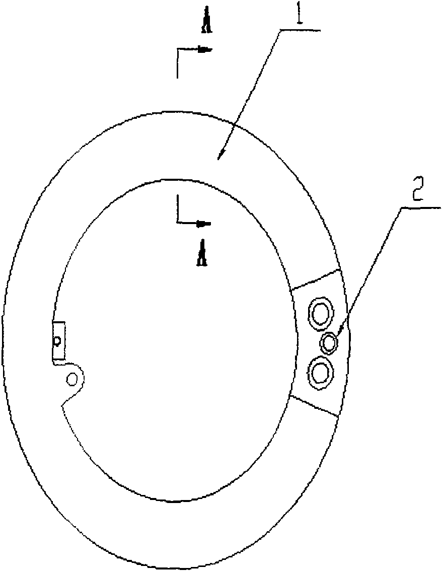
[0014] In this example, if figure 1 As shown, the lubricating oil cooler includes: a core body 1 and a fixing seat 2, both of which are arc-shaped, and the core body 1 and the fixing seat 2 are connected together by argon arc welding.
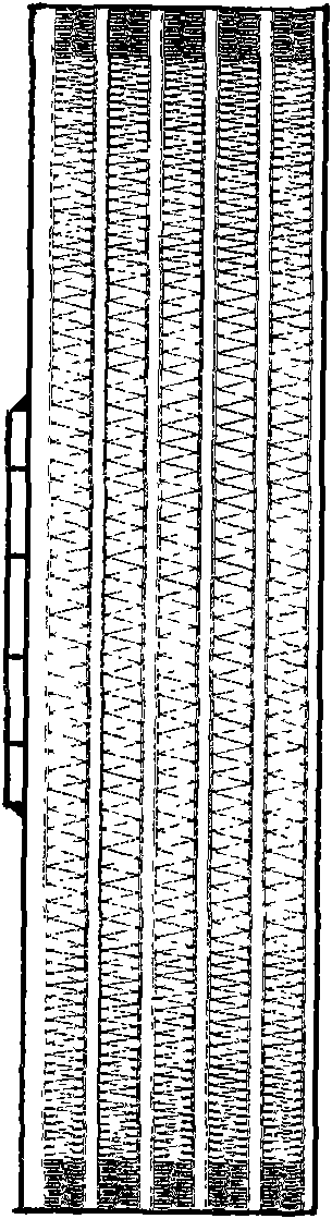
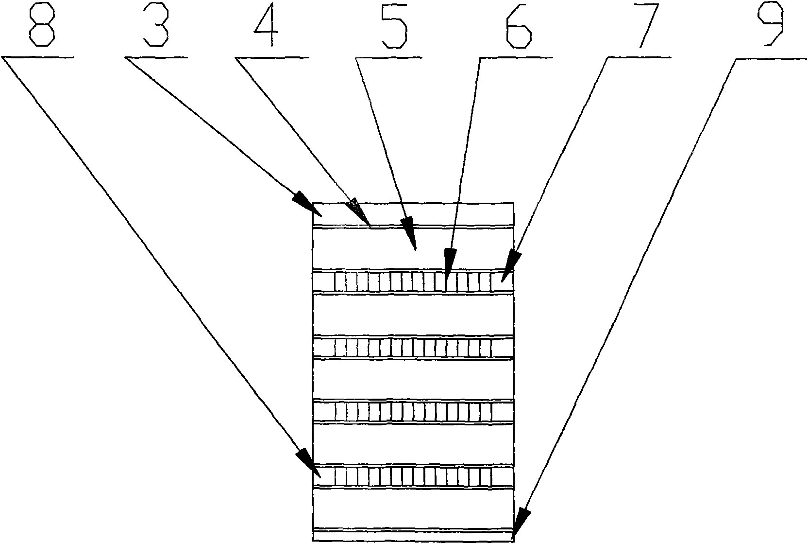
[0015] Such as image 3 As shown, the core body 1 is formed by brazing the upper cover plate 3, the partition plate 4, the outer fins 5, the inner fins 6, the inner seal 7, the outer seal 8 and the lower cover 9, etc., and the upper cover 3 Inner fins 6 and outer fins 5 are distributed parallel and alternately between the lower cover plate 9, and the inner fins 6 and outer fins 5 are the main heat dissipation elements; the upper cov...
PUM
 Abstract
Description
Claims
Application Information