Electronic expansion valve

A technology of electronic expansion valve and magnetic rotor, which is applied in the direction of lifting valve, valve details, valve device, etc., can solve the problems of easy looseness, low reliability, and easy cracking of the magnetic rotor, so as to reduce the possibility of cracking and improve reliability. sexual effect

Inactive Publication Date: 2011-04-27
ZHEJIANG SANHUA INTELLIGENT CONTROLS CO LTD
View PDF5 Cites 21 Cited by
  • Summary
  • Abstract
  • Description
  • Claims
  • Application Information

AI Technical Summary

Problems solved by technology

[0004] In the prior art, since the magnetic rotor is a highly brittle material, after the plastic component is pressed into the magnetic rotor, the magnetic rotor bears an outward radial force, and the magnetic rotor is easily broken due to excessive radial force; the plastic component relies on the magnetic The pressure between the rotor through holes is fixed in the magnetic rotor, which is prone to loosening
Electronic expansion valves in the prior art are less reliable

Method used


Image

  • Electronic expansion valve
  • Electronic expansion valve
  • Electronic expansion valve

Examples


Embodiment Construction

[0013] The present invention will be described in further detail below through specific embodiments and in conjunction with the accompanying drawings.

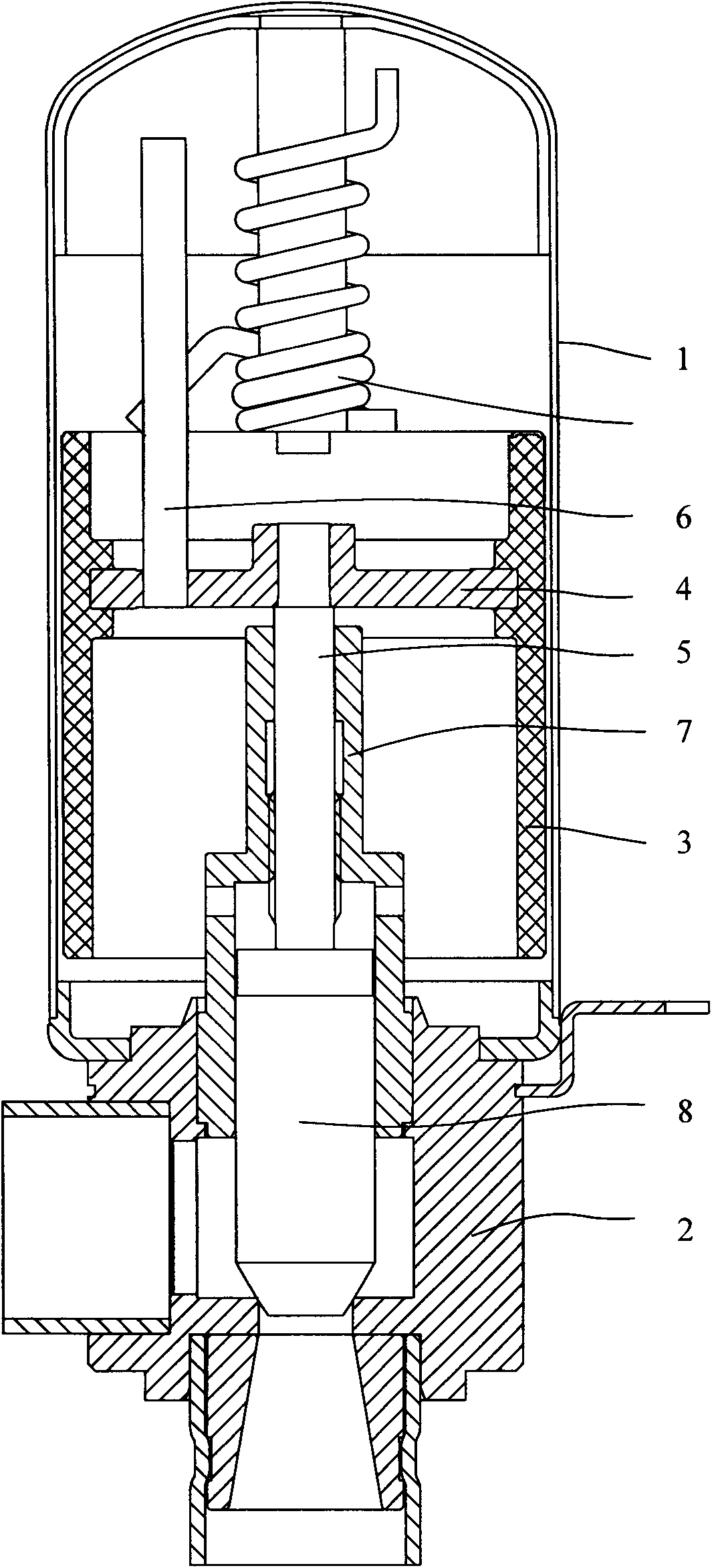
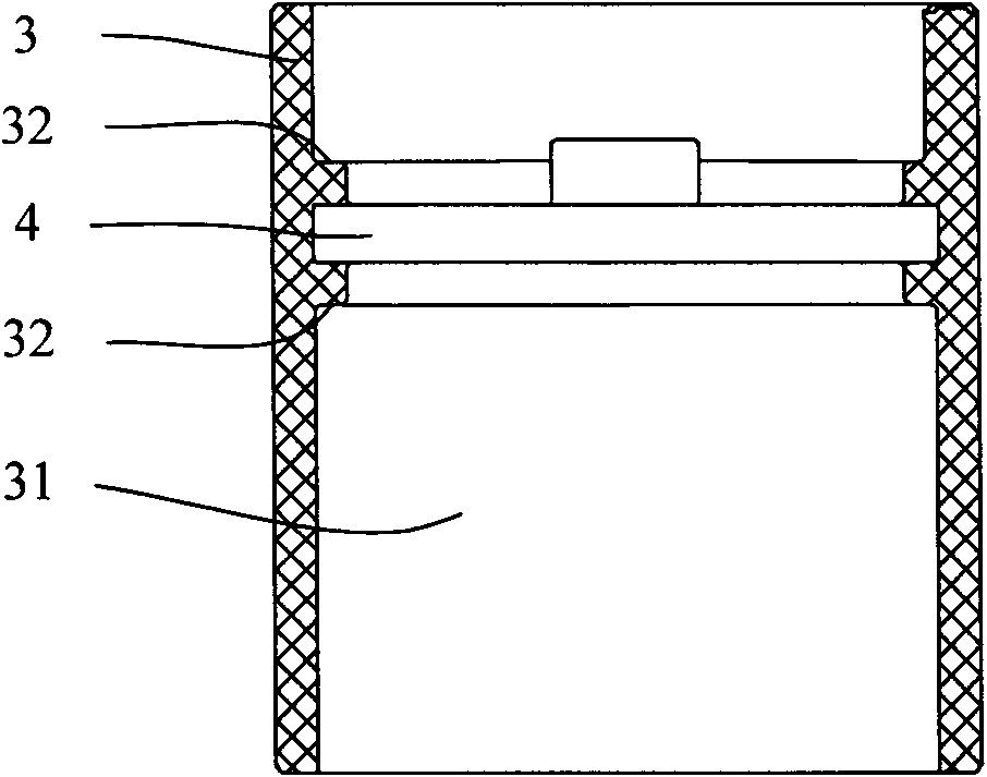
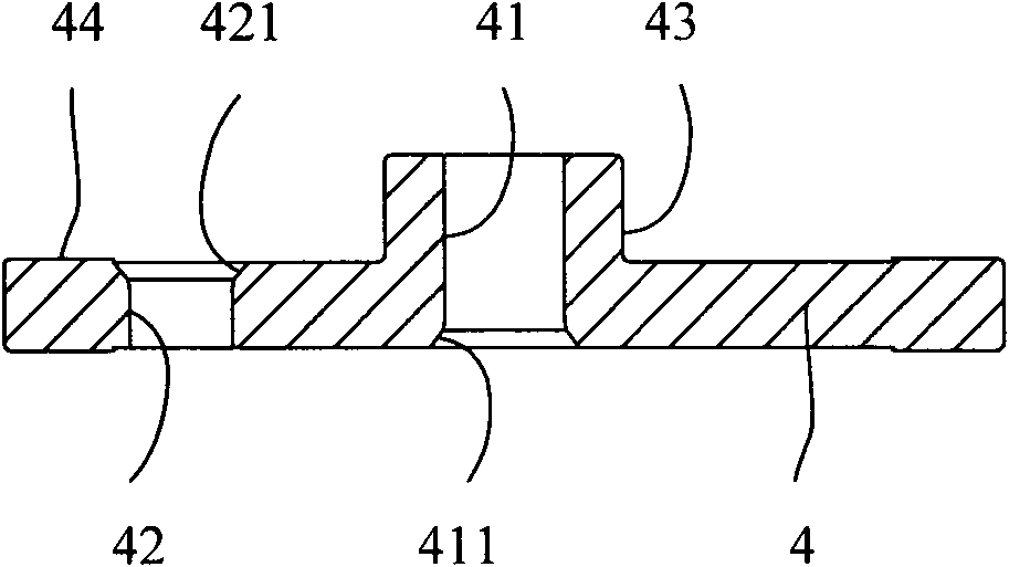
[0014] figure 1 It is a schematic structural diagram of an electronic expansion valve according to an embodiment of the present invention; figure 2 It is a schematic diagram of the assembly of the magnetic rotor and the connecting plate in the electronic expansion valve of the embodiment of the present invention; image 3 It is a cross-sectional view of the connecting plate in the electronic expansion valve of the embodiment of the present invention; Figure 4 It is a top view of the connecting plate in the electronic expansion valve according to the embodiment of the present invention. Such as figure 1 , figure 2 , image 3 and Figure 4 As shown, the electronic expansion valve in this embodiment includes a magnetic rotor 3 , a stop rod 6 and a screw 5 , the axis of the screw 5 coincides with the axis of the magnetic ...


PUM


Abstract

The embodiment of the invention provides an electronic expansion valve, comprising a magnetic rotor, a stop rod and a screw rod, wherein the axis of the screw rod is coincided with the axis of the magnetic rotor. The electronic expansion valve further comprises a connecting plate which is fixedly arranged in a through hole of the magnetic rotor, a first fixing hole is arranged at the center of the connecting plate, and the upper end part of the screw rod is fixedly arranged in the first fixing hole; a second fixing hole for fixing the stop rod is arranged on the connecting plate, and the lower end part of the stop rod is fixedly arranged in the second fixing hole; and the magnetic rotor drives the screw rod and the stop rod to rotate by the connecting plate. The stop rod, the screw rod and the magnetic rotor are firmly connected by the connecting plate which is fixedly arranged on the magnetic rotor, and the magnetic rotor is not influenced by the radial force of the connecting plate in the process that the stop rod and the screw rod are arranged on the magnetic rotor by the connecting plate, so as to reduce the possibility of cracking of the magnetic rotor owning to high radial force and improve the reliability of the electronic expansion valve.

Description

technical field [0001] Embodiments of the present invention relate to valve technology, in particular to an electronic expansion valve. Background technique [0002] The current electronic expansion valve uses the principle of a stepping motor to drive the magnetic rotor part to rotate forward and reverse with a coil, and convert the rotation of the magnetic rotor part into the up and down movement of the screw, and the screw drives the valve needle connected to it. Up or down to control the flow of the electronic expansion valve. [0003] The main structure of the electronic expansion valve in the prior art includes an outer cover, a valve seat, a nut, a valve needle, a screw rod, a magnetic rotor, a stop rod and the like. Wherein, the stop rod is injection-molded in a plastic assembly for installing the stop rod and the screw rod on the magnetic rotor. During the installation process of the electronic expansion valve, the screw rod is usually pressed into the installatio...

Claims


Application Information

Patent Timeline
Patent Type & Authority Applications(China)
IPC IPC(8): F16K31/06F16K1/02F16K1/32B22F3/12
Inventor 詹才意袁泽魏先让
Owner ZHEJIANG SANHUA INTELLIGENT CONTROLS CO LTD
Why Eureka
Try Eureka