LED bulb

A technology of LED light bulbs and LED chips, which is applied to lampshades, cooling/heating devices of lighting devices, lighting and heating equipment, etc. Fast, light coverage effects

Inactive Publication Date: 2011-04-27
DONGGUAN CITY MEINENG ELECTRONICS
View PDF6 Cites 15 Cited by
  • Summary
  • Abstract
  • Description
  • Claims
  • Application Information

AI Technical Summary

Problems solved by technology

However, most of the LED light-emitting columns of LED bulbs in the prior art are directly welded and packaged LEDs on the PCB (printed circuit board) substrate, and the LEDs are all located on one side of the PCB substrate, resulting in the LED light-emitting col

Method used


Image

  • LED bulb
  • LED bulb
  • LED bulb

Examples


Embodiment 1

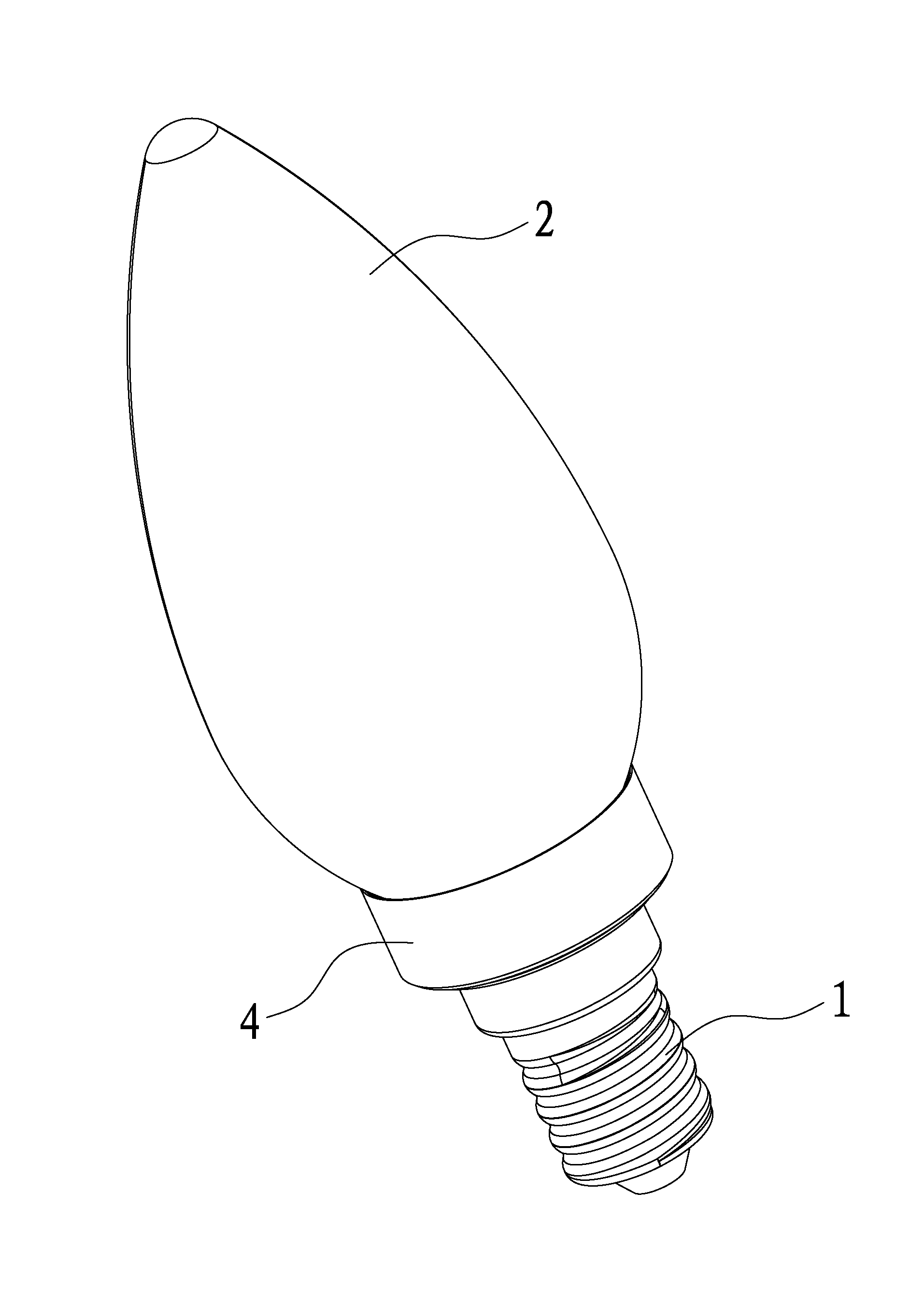
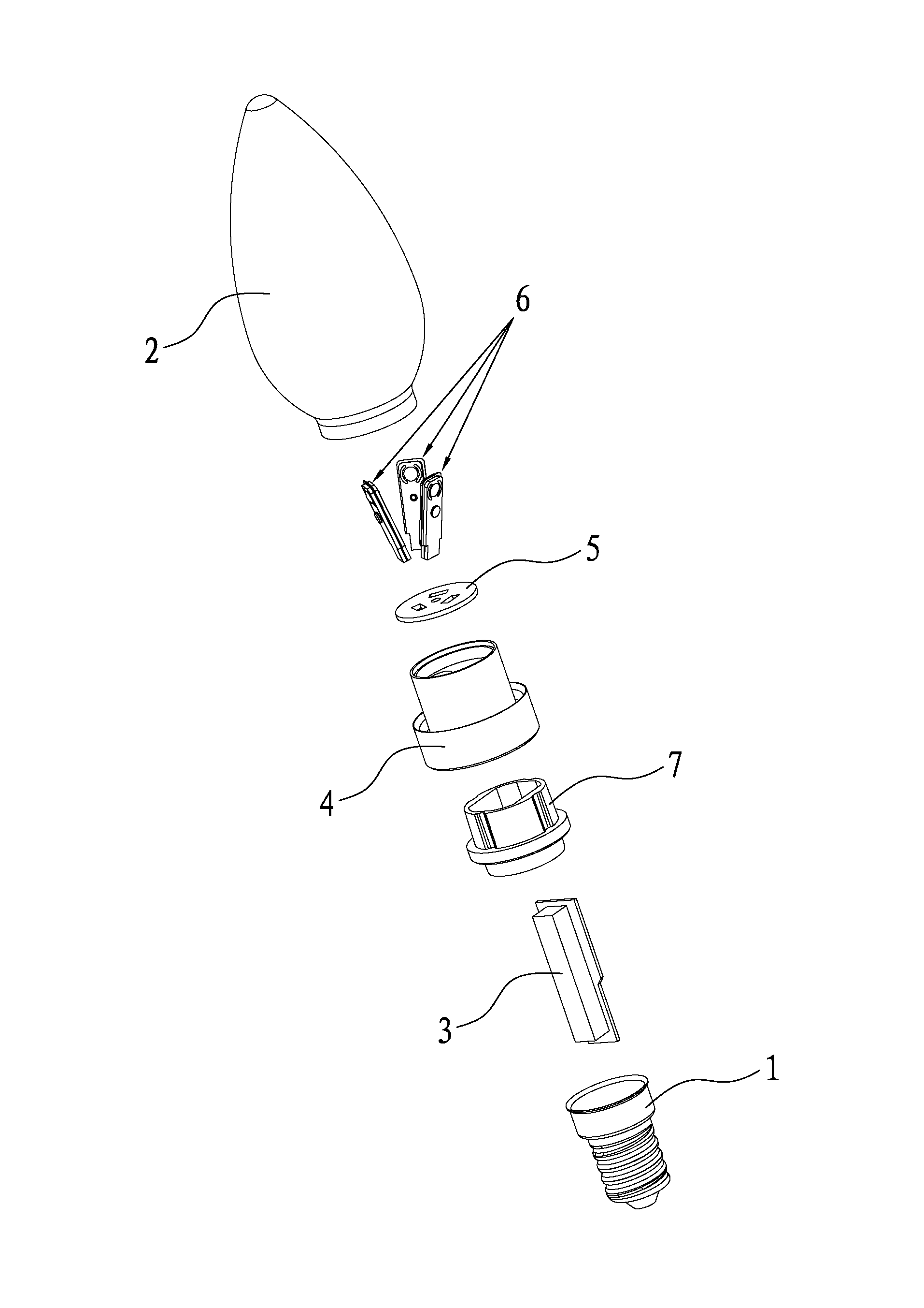
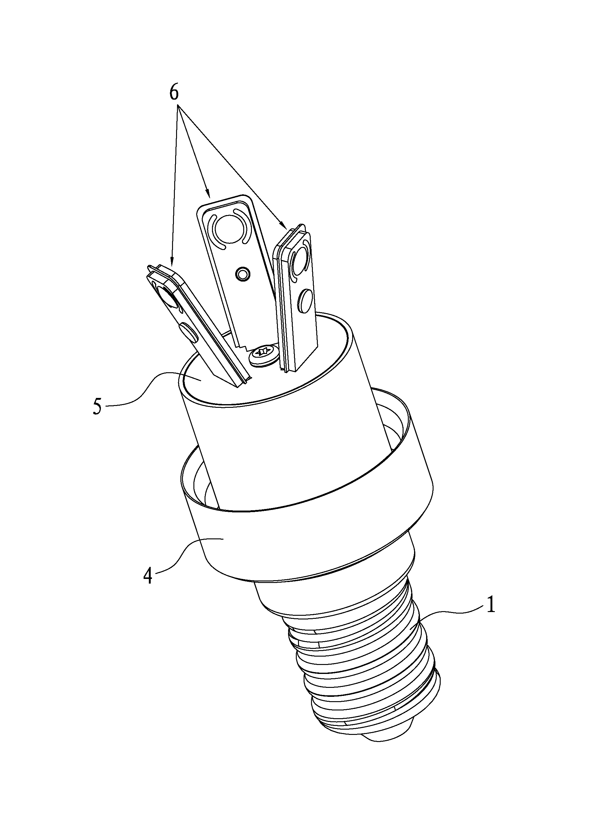
[0034] A kind of LED bulb of the present invention, as Figure 1~6 As shown, it includes a lamp cap 1, a lampshade 2, and a power supply 3 located in the lamp cap 1. The power supply 3 is electrically connected to the lamp cap 1, so that the power supply 3 can be connected to an external AC power through the lamp cap 1. A heat-dissipating metal is clamped between the lamp cap 1 and the lampshade 2. Shell 4, the top of the heat dissipation metal shell 4 is located in the lampshade 2, and the top of the heat dissipation metal shell 4 is clamped and fixed with a heat dissipation substrate 5, so that the heat dissipation substrate 5 can transfer heat to the heat dissipation metal casing 4, and the heat dissipation substrate 5 is plugged and fixed. LED luminous column 6, LED luminous column 6 comprises two PCB substrates 61, and the fronts of two PCB substrates 61 are all packaged with LED chip 62, namely LED chip 62 is directly packaged on PCB substrate 61, to reduce LED luminous c...

Embodiment 2

[0045] Embodiment 2 of an LED light bulb of the present invention. The difference between this embodiment and Embodiment 1 is that the lampshade 2 is a spherical lampshade, and the spherical lampshade can be selected as a glass spherical lampshade or a plastic spherical lampshade according to the actual application environment. It can also be a transparent spherical lampshade or a translucent spherical lampshade. Of course, the lampshade of the present invention can also be in other shapes, not limited to candle-shape or spherical shape. Other structures and working principles of this embodiment are the same as those of Embodiment 1, and will not be repeated here.


PUM


Abstract

The invention relates to technology for light-emitting diode (LED) lamps, in particular to an LED bulb. The LED bulb comprises a lamp holder, a lamp shade and a power supply positioned inside the lamp holder, wherein a radiating metal shell is clamped between the lamp holder and the lamp shade; the top of the radiating metal shell is positioned inside the lamp shade and is fixedly clamped with a radiating substrate; the radiating substrate is fixedly inserted with an LED luminous post; the LED luminous post comprises two printed circuit board (PCB) substrates; LED chips are packaged on front sides of the two PCB substrates and are electrically connected with the PCB substrates; the PCB substrates are electrically connected with the power supply; back surfaces of the two PCB substrates are fixedly adhered with each other; and a radiating sheet metal is sandwiched between the back surfaces of the two PCB substrates. The LED bulb can radially illuminate and has wide light ray coverage range and high radiating speed.

Description

technical field [0001] The invention relates to LED lamp technology, in particular to an LED light bulb. Background technique [0002] Because LED (Light Emitting Diode, light-emitting diode) has the characteristics of long service life, low energy consumption, and significant energy saving, LED has been widely used as a light source in daily life, such as cup lights, spotlights, car lights, LED Light bulbs and other LED lighting fixtures. [0003] At present, LED light bulbs generally include a lamp cap, a lampshade installed on the top of the lamp cap, and a power supply located in the lamp cap. An LED light-emitting column is arranged in the lampshade, and the LED light-emitting column is electrically connected to the power supply in the lamp cap. The light can be irradiated through the lampshade to achieve the purpose of lighting or decoration. However, most of the LED light-emitting columns of LED bulbs in the prior art are directly welded and packaged LEDs on the PCB...

Claims


Application Information

Patent Timeline
IPC IPC(8): F21S2/00F21V17/12F21V19/00F21V23/00F21V29/00F21V3/02F21Y101/02F21V29/70F21V29/89
Inventor 伍治华谢伊明林日辉邵小兵
Owner DONGGUAN CITY MEINENG ELECTRONICS
Why Eureka
Try Eureka