Balance measuring apparatus for tyre

A technology for measuring devices and tires, applied in measuring devices, static/dynamic balance testing, machine/structural component testing, etc., can solve problems such as the decline in dynamic balance measurement accuracy, achieve suppression of tilt or vibration, and improve measurement accuracy Effect

Active Publication Date: 2011-04-27
YAMATO SCALE CO LTD
View PDF7 Cites 15 Cited by
  • Summary
  • Abstract
  • Description
  • Claims
  • Application Information

AI Technical Summary

Problems solved by technology

Therefore, when the tire under test is held and rotated, the upper rim shaft is tilted or wobbled with respect to the lower rim shaft as the rotation drive shaft, which will cause a decrease in the measurement accuracy of the dynamic balance

Method used


Image

  • Balance measuring apparatus for tyre
  • Balance measuring apparatus for tyre
  • Balance measuring apparatus for tyre

Examples


Embodiment Construction

[0036] Hereinafter, embodiments of the present invention will be described with reference to the drawings.

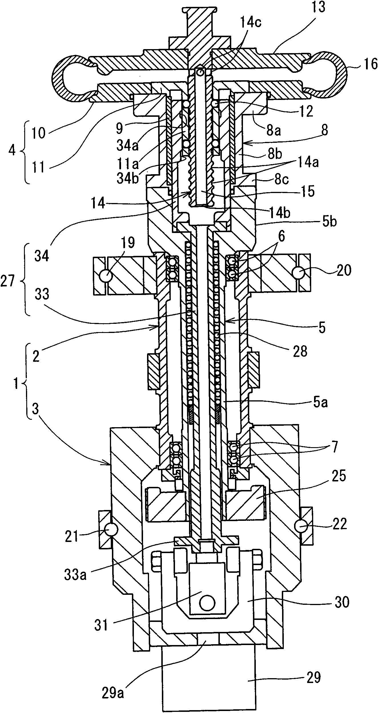
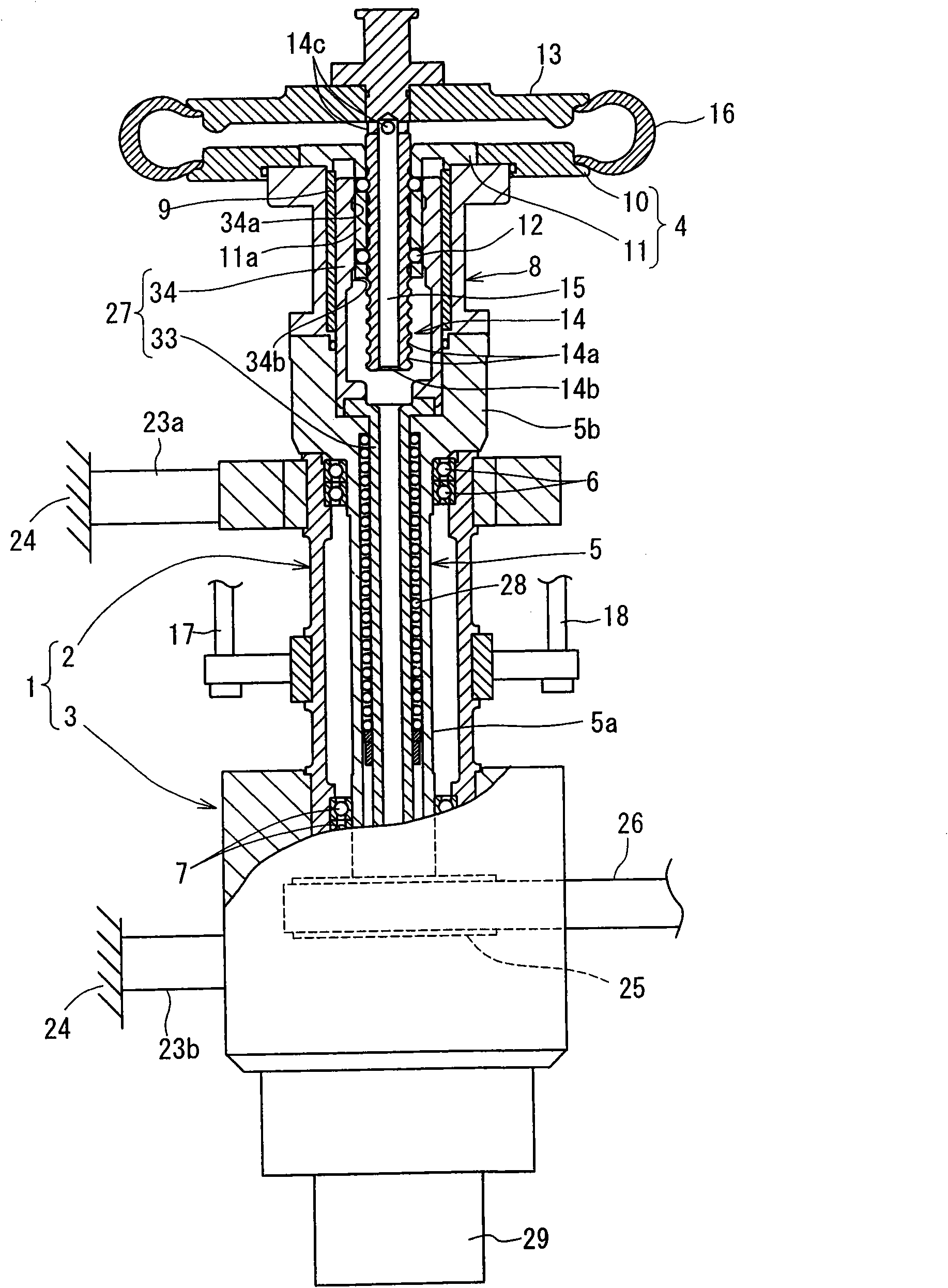
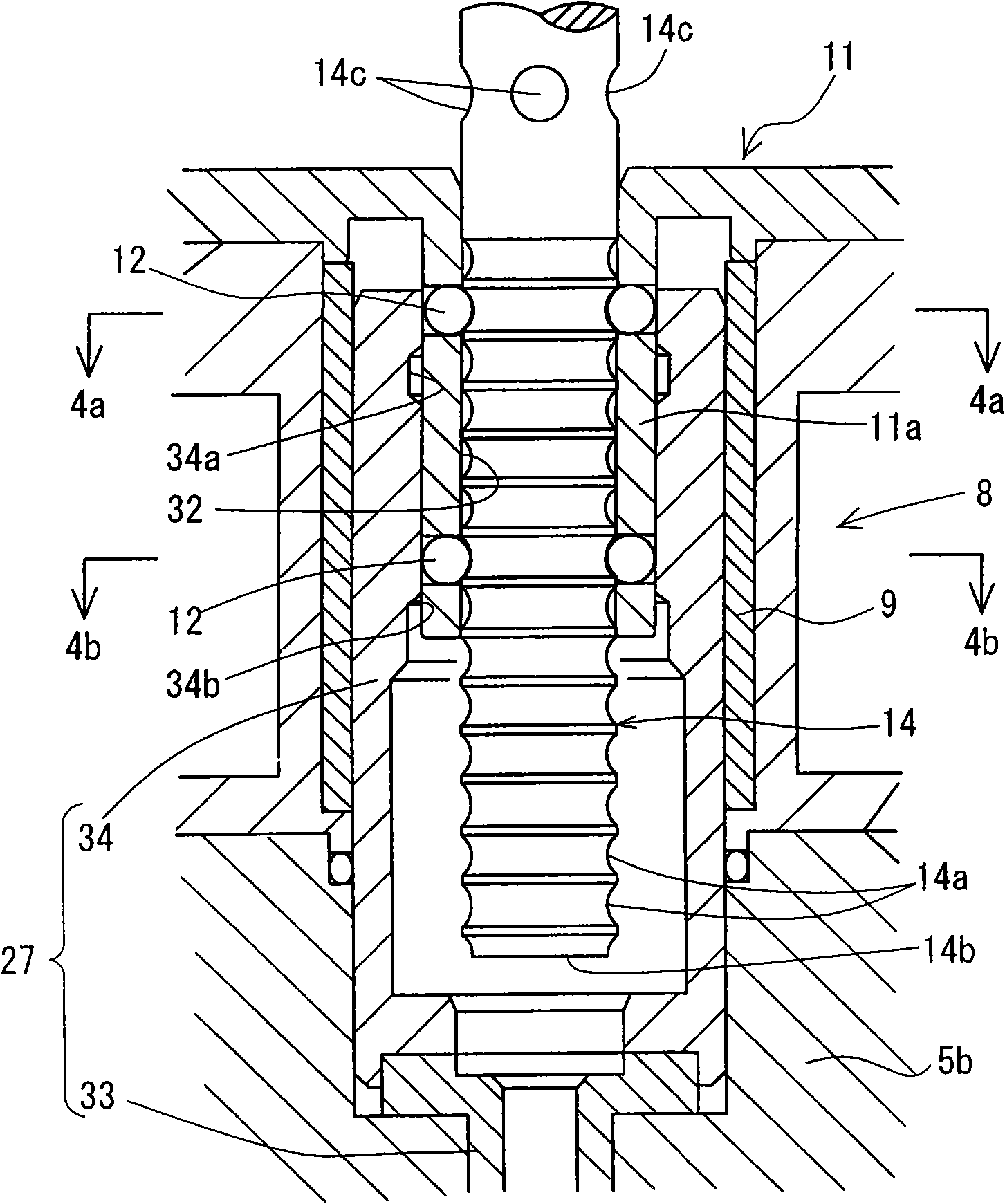
[0037] refer to Figure 1 to Figure 4(a) , FIG. 4(b) illustrates a tire dynamic balance measuring device according to an embodiment of the present invention. figure 1 It is a longitudinal sectional view of a dynamic balance measuring device for tires, figure 2 for viewing from the side figure 1 A partial cutaway view of the device, image 3 for figure 1 The partial enlarged view of the important part of , Fig. 4(a) is from image 3 The sectional view of section line (4a)-(4a) observation, Fig. 4(b) is from image 3 The cross-sectional view observed by the section line (4b)-(4b).

[0038] In these drawings, the tire dynamic balance measurement device according to the embodiment includes a housing 1 supported in a vertical state on a frame (not shown). The casing 1 is composed of a cylindrical upper casing 2 and a lower casing 3 .

[0039]The hollow rotating shaf...


PUM


Abstract

The invention discloses a balance measuring apparatus for tyre so disposed that a upper rim shaft is inserted an insertion hole of a driving shaft which is rotarily driven by a lower rim shaft, and a hollow operation sleeve slides to a cooperation position, a plurality of balls (12) in the upper and lower parts of the circumferential wall which is maintained on the driving shaft and on which the insertion hole is formed being configured to match an annular groove (14a) which is formed on the peripheral surface of the upper rim shaft (14), so that the upper rim shaft (14) is firmly locked circumferentially at the upper and lower positions. In rotation, the invention can inhibit inclination or vibration and swinging of the upper rim shaft (14) in order to increase measuring accuracy.

Description

technical field [0001] The present invention relates to a dynamic balance measuring device for tires. The device uses a lower rim mounted on a rotatably supported lower rim shaft and an upper rim arranged at a position opposite to the lower rim to be rotatably supported. The tire to be tested rotates integrally while being held between the two, and the dynamic balance of the tire to be tested can be measured. Background technique [0002] The tire dynamic balance measuring device generally includes a lower rim vertically supported by a bearing and driven to rotate on a lower rim shaft, and an upper rim that can be raised and lowered and freely rotated on the upper side opposite to the lower rim, When measuring the dynamic balance of the tire under test, the tire can be integrally rotated in a state where the tire under test is held between these two rims. In addition, in this dynamic balance measurement, in order to allow the upper rim and the lower rim to rotate integrally...

Claims


Application Information

Patent Timeline
Patent Type & Authority Applications(China)
IPC IPC(8): G01M1/16
Inventor 中山和夫宫崎晋一
Owner YAMATO SCALE CO LTD
Why Eureka
Try Eureka