Electric lifting stator inner cavity cyclometer

A technology of stator inner cavity and driving device, applied in mechanical counter/curvature measurement and other directions, can solve the problems of inability to guarantee the quality of motor stator assembly, time-consuming and laborious operation and low measurement accuracy, etc. Convenience and the effect of improving measurement accuracy

Active Publication Date: 2011-05-04
HANGZHOU FROMO ELECTROMECHANICAL TECH
View PDF1 Cites 15 Cited by
  • Summary
  • Abstract
  • Description
  • Claims
  • Application Information

AI Technical Summary

Problems solved by technology

[0004] The purpose of the present invention is to provide a measuring arm that can freely rotate along the central column and is controlled by a driving device to move up and down along the central column, which is easy to operate and use, and has high measurement efficiency and measurement accuracy, thereby ensuring the assembly quality of the motor stator. The cavity circle measuring device solves the technical problems in the prior art that the operation and use of the measuring device is time-consuming, poor in stability, and low in measurement accuracy, so that the assembly quality of the motor stator cannot be guaranteed.

Method used


Image

  • Electric lifting stator inner cavity cyclometer
  • Electric lifting stator inner cavity cyclometer
  • Electric lifting stator inner cavity cyclometer

Examples


Embodiment 1

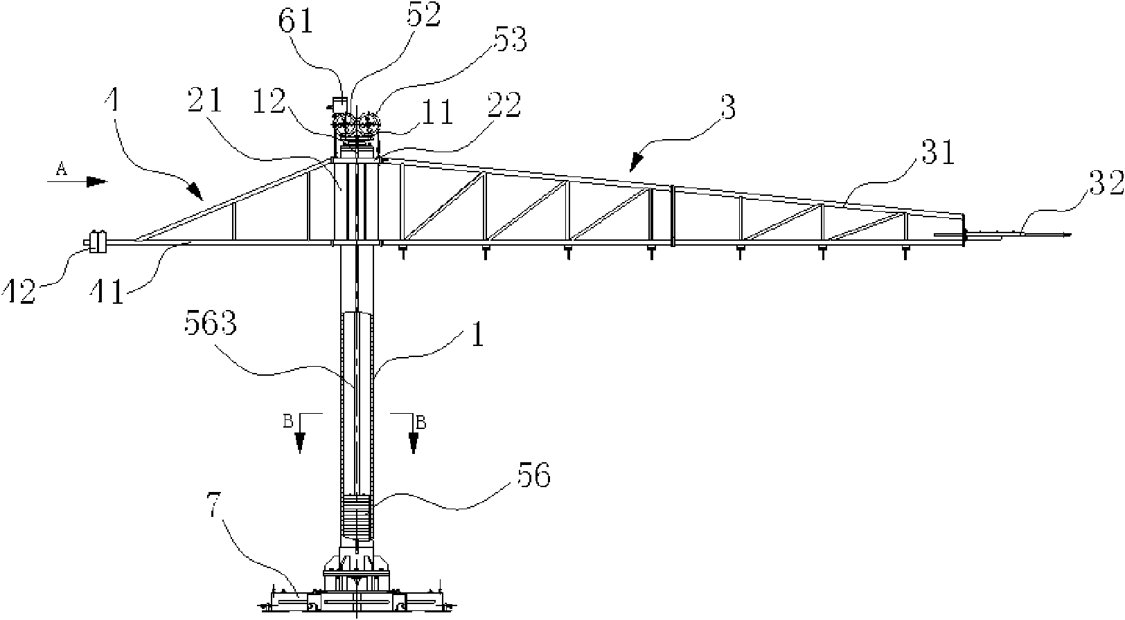
[0022] like figure 1 As shown, a stator inner cavity circle measuring device for electric lifting includes a base 7 and a central column 1 vertically fixed on the base 7 in a tubular structure. A sliding frame 2 is set on the central column 1, and a The measuring arm 3 and the balance arm 4 are respectively connected by bolts on both sides along the horizontal direction. The sliding frame 2 together with the measuring arm 3 and the balance arm 4 can rotate and slide up and down along the center column 1. The transmission mechanism connected to the device can drive the sliding frame 2 to slide up and down along the central column 1 under the drive of the driving device.

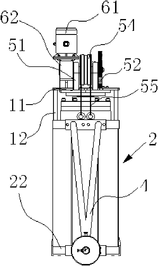
[0023] like figure 2 As shown, a top plate 11 is coaxially connected to the upper end of the central column 1 through an axial thrust bearing, and the driving device and transmission mechanism are installed on the top plate 11. The driving device includes a motor 61 and a reducer 62 connected with the motor ...

Embodiment 2

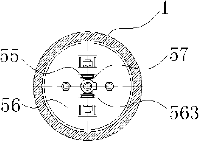
[0028] like Figure 4 As shown, a sprocket 58 is respectively set on the rotating shafts of the driving gear 52 and the driven gear 53 between the two support plates 51, and the two sprockets 58 are relatively arranged in the same vertical plane, corresponding between the two rotating shafts. A counterweight 56 ​​is housed in the cavity of the tubular central column 1 below the sprocket 58. On both sides of the two rotating shafts, a sliding frame 2 is set on the tubular central column 1 corresponding to the sprocket 58 below. A chain 59 is respectively installed on the 58, and the inner end of the corresponding chain 59 is hingedly connected with the counterweight 56 ​​end face downwards, and the outer end is hingedly connected with the sliding frame 2 downwards, and the counterweight 56 ​​and the sliding frame 2 are suspended by the chain 59. On both sides of the sprocket 58, the chains 59 are symmetrically distributed on the end face of the sliding frame 2, and the remainin...


PUM


Abstract

The invention relates to an electric lifting stator inner cavity cyclometer, which provides a stator inner cavity cyclometer with the advantages of convenience for operation and use and high measuring efficiency and accuracy, wherein a measuring arm of the stator inner cavity cyclometer can freely rotate along a center post, and is driven by a driving device to lift up and down along the center post so that the assembly quality of a motor stator can be ensured and the technical problem that the assembly quality of the motor stator cannot be ensured because of time and labor consumption in operation and use, poor stability and low measuring accuracy of measuring devices of the prior art. The electric lifting stator inner cavity cyclometer comprises a base and a center post arranged on the base, wherein the center post is provided with a measuring arm and a balance arm; a sliding rack which can rotate along the center post is sheathed on the center post in a sliding mode; both sides of the sliding rack are respectively connected with the measuring arm and the balance arm; and a transmission mechanism is arranged above the center post, is connected with the driving device and can drive the sliding rack to upward and downward slide along the center post.

Description

technical field [0001] The invention relates to a stator inner cavity circle measuring device, in particular to an electric lifting stator inner cavity circle measuring device. Background technique [0002] The stator and rotor on the motor are important parts on the motor, and the roundness of the inner cavity of the stator is a necessary condition to ensure the normal operation of the motor. The stator on the small motor often uses a special inner circle measurement tool, but for large motors, especially For large and medium-sized hydroelectric generators, the measurement method commonly used at present is to hoist the measuring arm with a stable arm on the central column, and push the measuring arm to drive the central column to rotate on the fixed base to complete the inner circle measurement within a single circle. , and manually adjust the height of the measuring arm on the central column to change the measuring position as needed. Due to the large volume and weight of...

Claims


Application Information

Patent Timeline
Patent Type & Authority Applications(China)
IPC IPC(8): G01B5/20
Inventor 徐文峰曾小明
Owner HANGZHOU FROMO ELECTROMECHANICAL TECH
Why Eureka
Try Eureka