Calendar mechanism and analog timepiece equipped with same mechanism

A calendar and date technology, which is applied in the field of calendar mechanisms and pointer clocks, can solve problems such as inability to display the date, date text deviation, etc.

Inactive Publication Date: 2011-05-04
SEIKO INSTR INC
View PDF6 Cites 4 Cited by
  • Summary
  • Abstract
  • Description
  • Claims
  • Application Information

AI Technical Summary

Problems solved by technology

[0003] However, in the calendar mechanism proposed in this patent document 1, the specific cam surface (for example, the date of 01 to 09) between the one end portion of the driven lever portion of the drive cam lever and the specific cam surface portion of the drive cam portion of the first date wheel corresponding regions), although it is necessary for the first and second sector gear parts to mesh with each other through the teeth at their respective specific positions corresponding to this state (it is necessary that the mutual rotational phases coincide with each other). Indispensable), but in the state (inconsistent state) that does not satisfy the condition even if only one tooth is offset, the first and second date wheels and the driving cam lever are spliced ​​together, and the calendar in this inconsistent state In the mechanism, the date characters on the second date wheel are deviated, and the proper date cannot be displayed, and impossible dates such as "32" to "39" are displayed

Method used


Image

  • Calendar mechanism and analog timepiece equipped with same mechanism
  • Calendar mechanism and analog timepiece equipped with same mechanism
  • Calendar mechanism and analog timepiece equipped with same mechanism

Examples


Embodiment

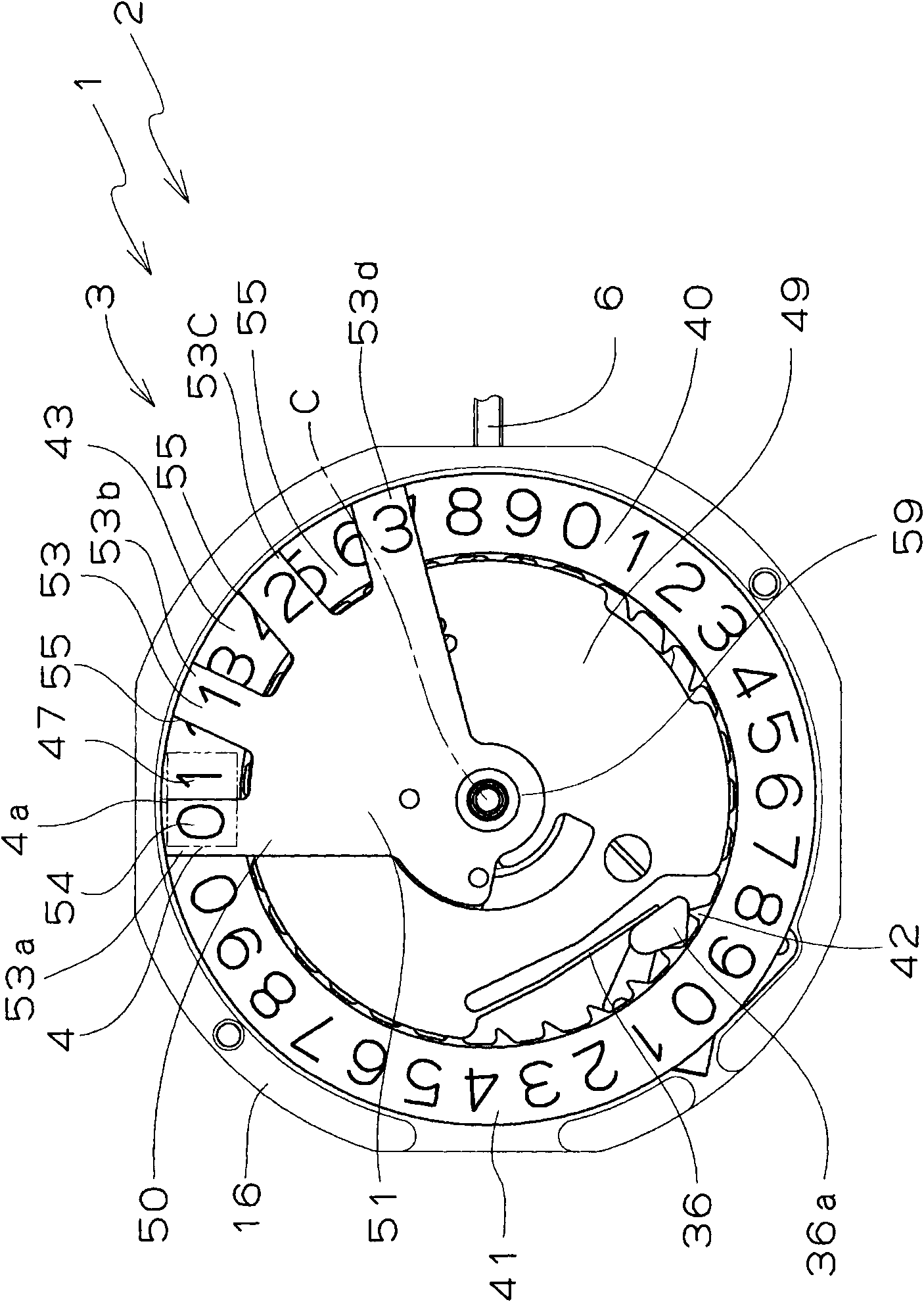
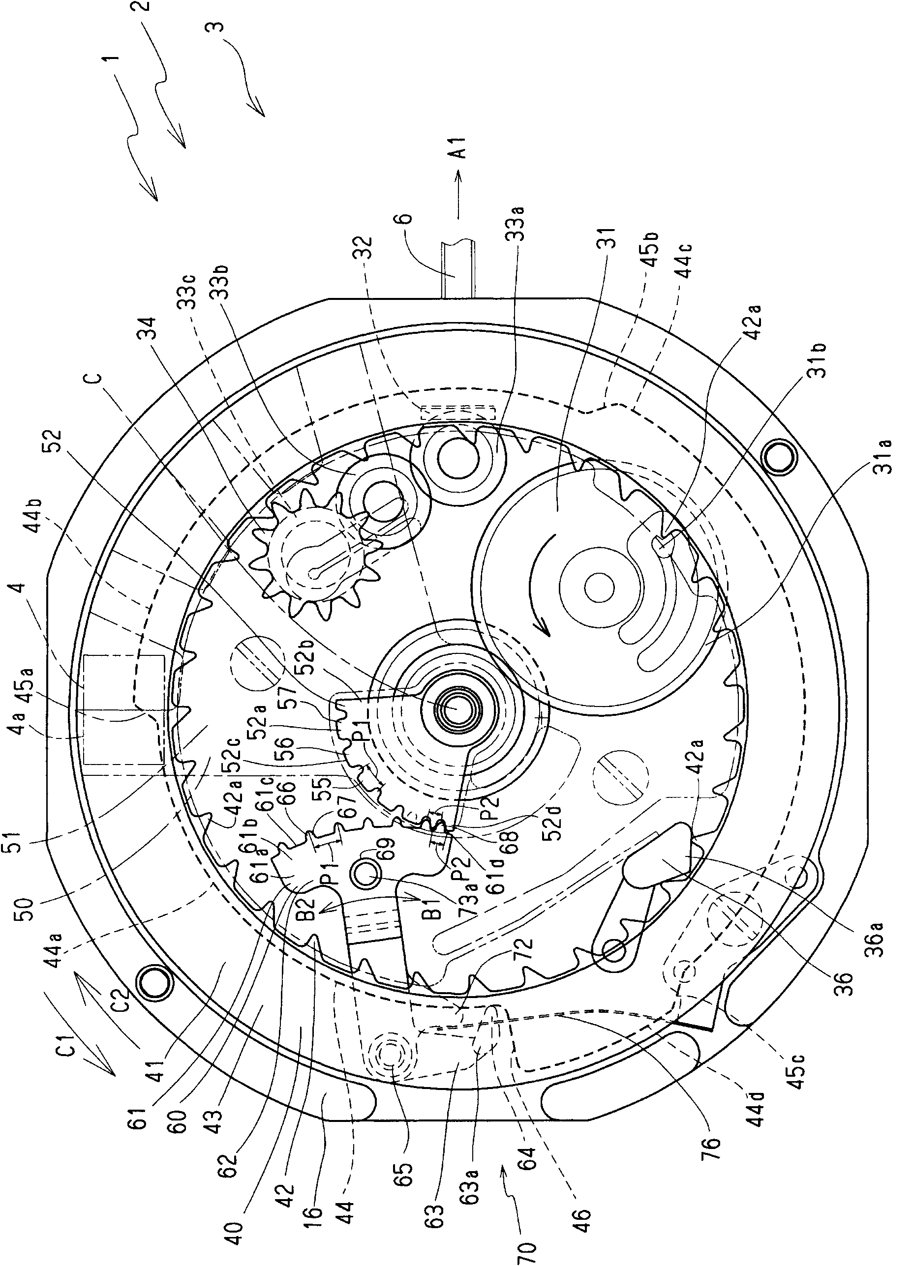
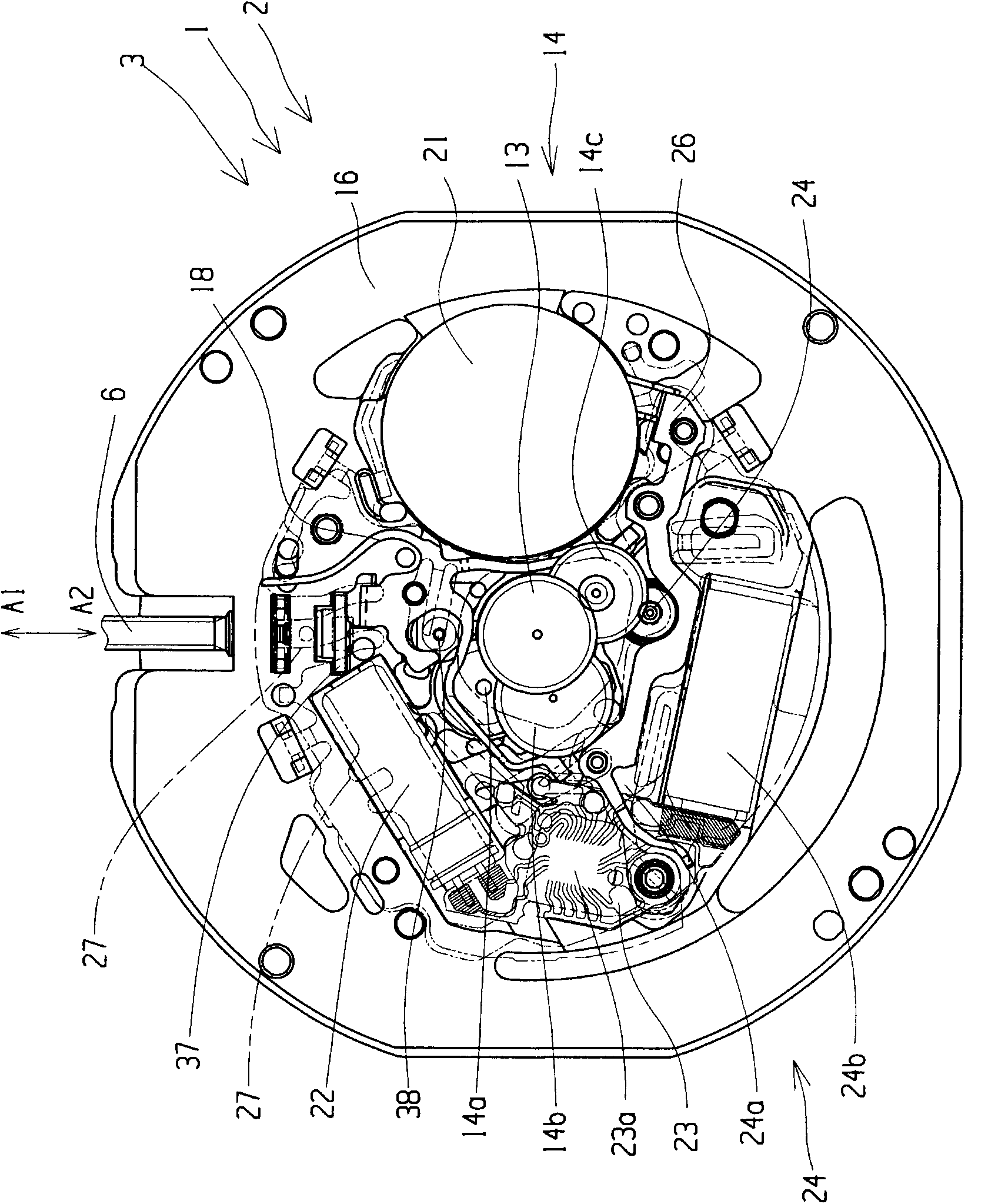
[0038] An analog timepiece 2 of a preferred embodiment of the present invention having a calendar mechanism 1 of a preferred embodiment of the present invention generally has the following image 3 as well as Figure 4 A timepiece body or movement 3 of the structure shown.

[0039] Mainly from Figure 4 It can be seen that the movement 3 of the analog timepiece 2 has: the hour wheel 11 , the minute wheel 12 and the second wheel 13 , which can freely rotate around the central axis C. In addition, in the representation of the appearance Figure 6 Among them, reference numeral 6a denotes the crown. The gears 11a, 11b, 12a, 12b, 13a, 13b of the hour wheel 11, the minute wheel 12, and the second wheel 13 pass through such as image 3 The illustrated gear train 14 is intermeshed with a wheel 14a, a third wheel 14b, and a fifth wheel 14c. The hour hand 11d is installed at the end of the barrel 11c of the hour wheel 11 near the dial 5 side, the minute hand 12d is installed at the...


PUM


Abstract

The present invention provides a calendar mechanism which can easily and reliably cause first and second date indicators to coincide in rotation phase, and an analog timepiece equipped therewith. The calendar mechanism of the analog timepiece includes a first date indicator (40) including a first date character indication portion which indicates the ones column of the date, a first date indicator gear portion, and a drive cam portion which defines an endless ring-shaped cam face; a drive cam lever (60) which includes a driven lever portion (63) whose one end portion abuts against the drive cam portion, and an operating lever portion (62) which includes a first fan-shaped gear portion at the leading end portion, the operating lever portion being pivoted in accordance with the driven lever portion; and a second date indicator (50) which, being rotatable, includes a second date character indication portion (53) which indicates the tens column of the date, and a second fan-shaped gear portion (52) meshing with the first fan-shaped gear portion. The first fan-shaped gear portion and second fan-shaped gear portion have specified teeth (68, 58) which are brought into selective meshing engagement in a condition in which the first date indicator and second date indicator coincide in rotation phase.

Description

technical field [0001] The present invention relates to a calendar mechanism and an analog clock with the calendar mechanism, and more particularly to a so-called Big Date (Big Date) that uses its own date wheels to display the ones and tens dates respectively, and as a result, the date can be displayed in large characters. ) style calendar mechanism and an analog clock with the calendar mechanism. Background technique [0002] As a calendar mechanism with a large date style, the following calendar mechanism has been proposed (for example, Patent Document 1). The date wheel gear part and the driving cam part, the first date character display part is used to display the single digit date in the date, and the first date wheel gear part is formed on the inner circumference of the first date character display part and received Torque action, the drive cam part is formed on the back side of the first date character display surface and defines an endless ring-shaped cam surface; ...

Claims


Application Information

Patent Timeline
Patent Type & Authority Applications(China)
IPC IPC(8): G04B19/253
CPCG04B19/247
Inventor 平野圭
Owner SEIKO INSTR INC
Why Eureka
Try Eureka