AI technical title is built by Patsnap AI team. It summarizes the technical point description of the patent document.
A parking assistance and panoramic technology, which is applied in closed-circuit television systems, image data processing, instruments, etc., can solve problems such as poor adaptability of camera vibrations
Active Publication Date: 2013-07-31
GUANGZHOU ZHIYUAN ELECTRONICS CO LTD
View PDF2 Cites 1 Cited by
Summary
Abstract
Description
Claims
Application Information
AI Technical Summary
This helps you quickly interpret patents by identifying the three key elements:
Problems solved by technology
Method used
Benefits of technology
Problems solved by technology
[0004] Patent application number 200810163310.X proposes a calibration method for a panoramic assisted parking system. Zhang Zhengyou’s camera calibration method is used to calculate the internal and external parameters of the camera. However, when stitching images, the splicing method with fixed positions is used. The adaptability to different models and camera vibration is not strong
Patent application number 200910119475.1 proposes a panoramic visual parking system, which uses an FPGA chip for video processing and synthesis, but requires another MCU chip for co-processing
Method used
Image
Click on the blue label to locate the original text in one second.
Reading with bidirectional positioning of images and text.
Examples
no. 1 example
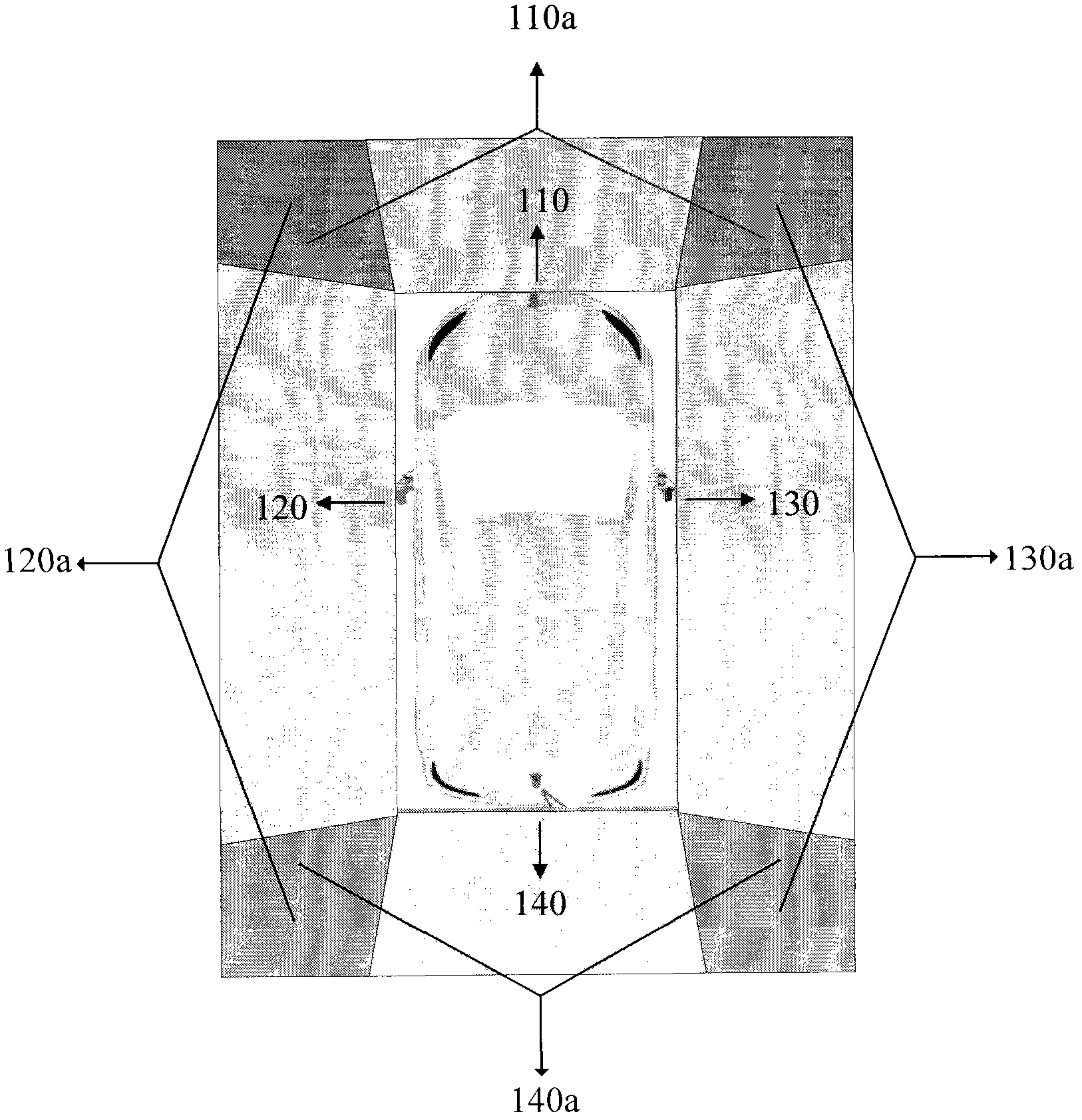
[0093] This embodiment uses four 180-degree ultra-wide-angle cameras to implement the functions of the present invention.
[0094] image 3 This is an illustration of the implementation principle and camera shooting range of the present invention when the four cameras are implemented. Four 180-degree ultra-wide-angle cameras 110, 120, 130, and 140 are respectively installed under the front car logo, the rear compartment handle, and the two side mirrors. , The four shooting areas captured are 110a, 120a, 130a, and 140a. Since the angles of the four cameras are close to 180 degrees, the viewing angles of the shooting areas 110a, 120a, 130a, and 140a of the four cameras are large, which provides conditions for forming a 360-degree panoramic image. In order to obtain all the images around the car body, the images taken by the four cameras have overlapping parts on the borders, and these overlapping parts will be processed during image synthesis and stitching.
[0095] Figure 4 Shows ...
no. 2 example
[0098] This embodiment uses eight 180 ultra-wide-angle cameras to implement the functions of the present invention.
[0099] Because the bodies of large trucks, buses, and construction vehicles are relatively long, it is difficult for the driver to see the rear and side of the vehicle. However, if only four cameras are installed, it is difficult to cover the 360-degree surrounding scenery. Therefore, this implementation The example uses eight cameras to solve implementation problems on large vehicles.
[0100] Image 6 This is a schematic diagram of the present invention when it is implemented with eight cameras. The cameras 301, 302, 303, 304 and the four cameras are installed at the same location when implemented, and the cameras 305, 306, 307, and 308 are installed near the four diagonal corners of the vehicle body, so that the cameras can get the full view.
[0101] Figure 7 It is a hardware structure block diagram when the present invention is implemented with eight cameras. ...
PUM
Abstract
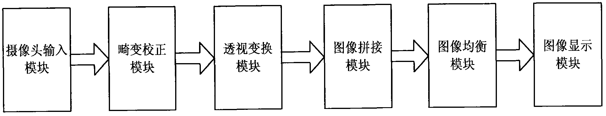
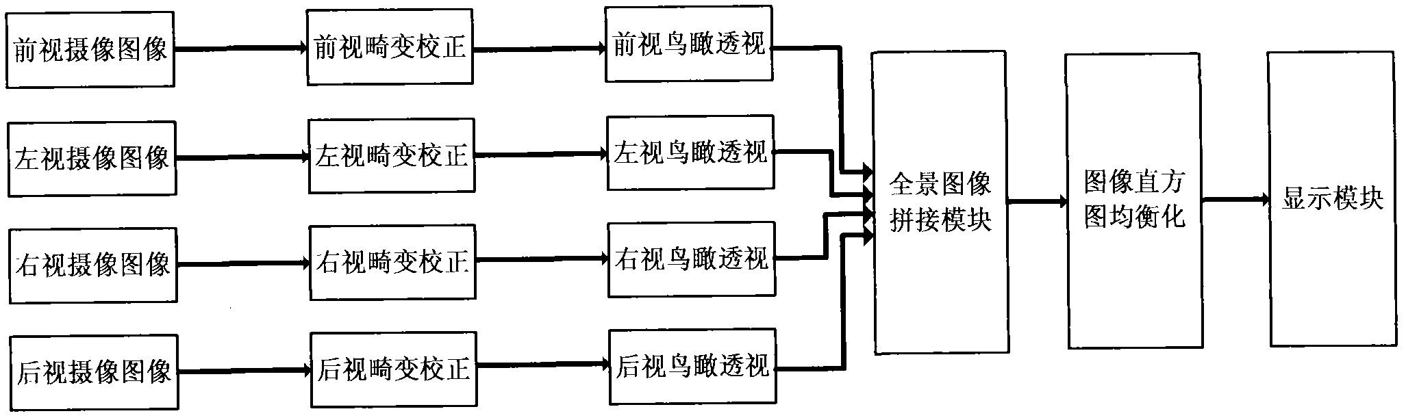
The invention discloses a panoramic parking assist system, which is a technique applied to the fields of automotive electronics and auto safety driving assistance. The system comprises a camera input module, an image correction module, a bird-eye perspective module, an image mosaicking module, a histogram equalization module and an image display module. The system is used for effectively solving the problem of car crash accidents caused by that the driver can not fully observe the situations around the car in the process of parking. By using the system, a 360-degree top view around a car bodyin real time can be showed for the drivers, so that the drivers can clearly see the relative positions of obstacles around the car body and the distances between the obstacles and the car body; and the blind visual areas around the car body can be eliminated so as to improve the security and stability of car in the process of parking. Through integrating a plurality of machine vision and digital image processing algorithms and fusing a plurality of advanced techniques in the field of machine vision, and based on the advantages of low cost, high performance, strong portability and the like, the system is convenient to be popularized and applied widely.
Description
Technical field [0001] The invention relates to visually displaying the surrounding conditions of the car to the driver to improve the safety and stability of car parking, and belongs to the field of automotive electronics and machine vision, in particular to the field of car safety assisted driving. Background technique [0002] In recent years, with the rapid development of the automobile industry and the continuous improvement of people's living standards, the number of automobiles in my country is increasing year by year. At the same time, the proportion of non-professional car drivers among car drivers has also increased year by year. When reversing in crowded and narrow places such as highways, streets, parking lots, garages, etc., the driver has to look forward and look back. A car collision will happen if he is not careful. [0003] Therefore, various car driving assistance systems have emerged, such as the reversing radar system for ultrasonic ranging, setting up a camera...
Claims
Application Information
Patent Timeline
Application Date:The date an application was filed.
Publication Date:The date a patent or application was officially published.
First Publication Date:The earliest publication date of a patent with the same application number.
Issue Date:Publication date of the patent grant document.
PCT Entry Date:The Entry date of PCT National Phase.
Estimated Expiry Date:The statutory expiry date of a patent right according to the Patent Law, and it is the longest term of protection that the patent right can achieve without the termination of the patent right due to other reasons(Term extension factor has been taken into account ).
Invalid Date:Actual expiry date is based on effective date or publication date of legal transaction data of invalid patent.

